
Toilet odor removal system

a technology for removing odors and toilets, applied in the field of toilet odor removal systems, can solve the problems of significant and expensive modifications to the approach, difficult to remove odors from toilets, and difficult to remove odors,

Inactive Publication Date: 2013-10-10
PRETE ROY A +1
View PDF7 Cites 8 Cited by
  • Summary
  • Abstract
  • Description
  • Claims
  • Application Information

AI Technical Summary

Benefits of technology

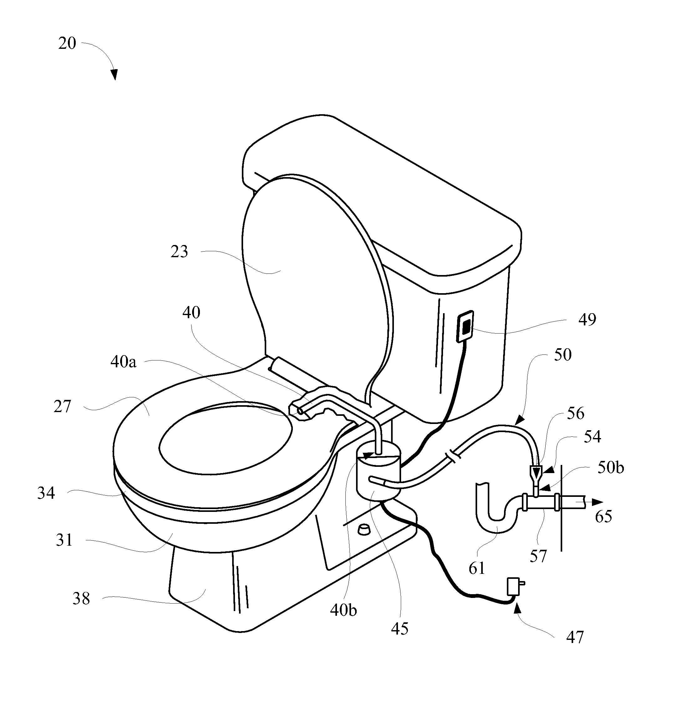
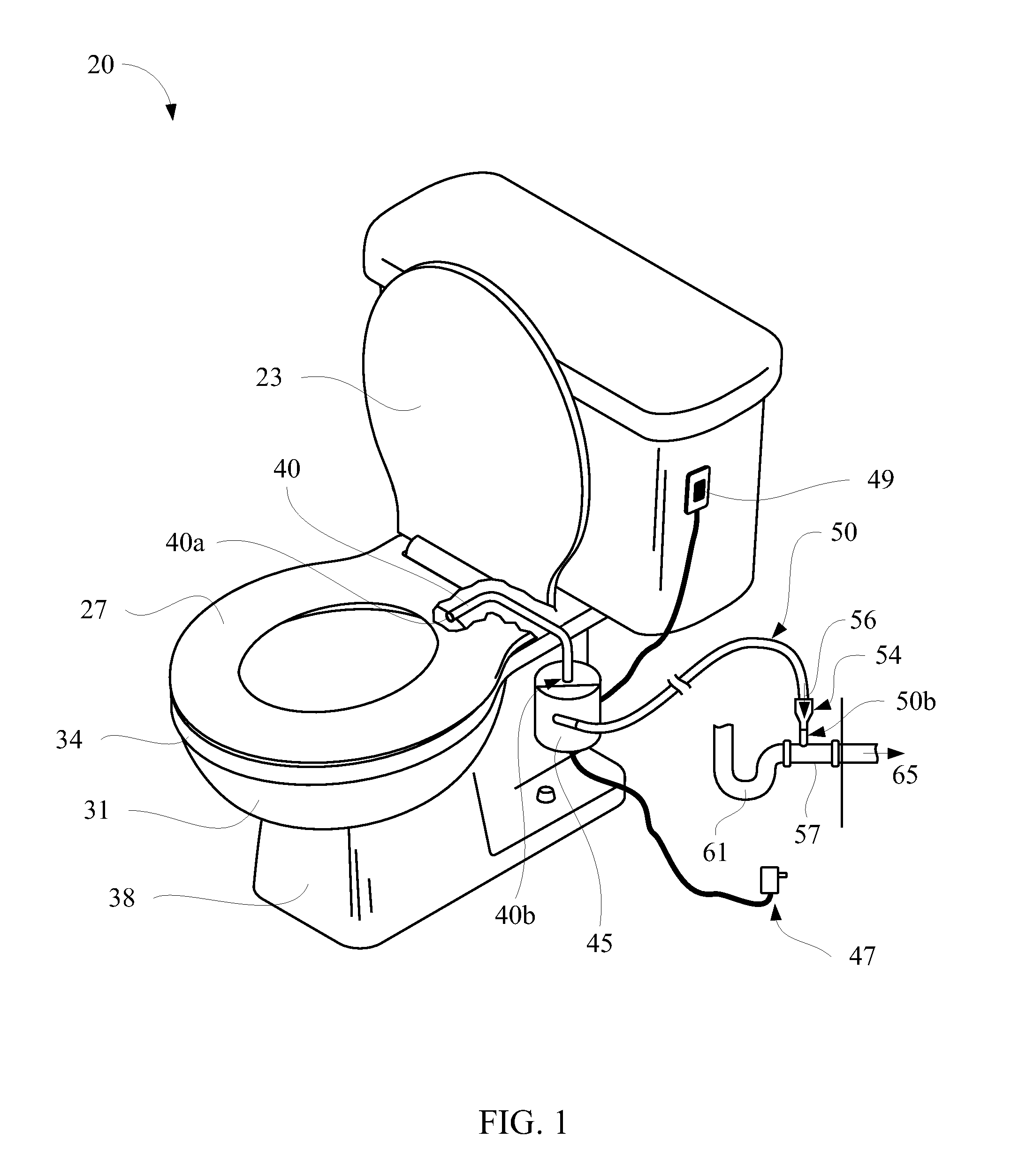
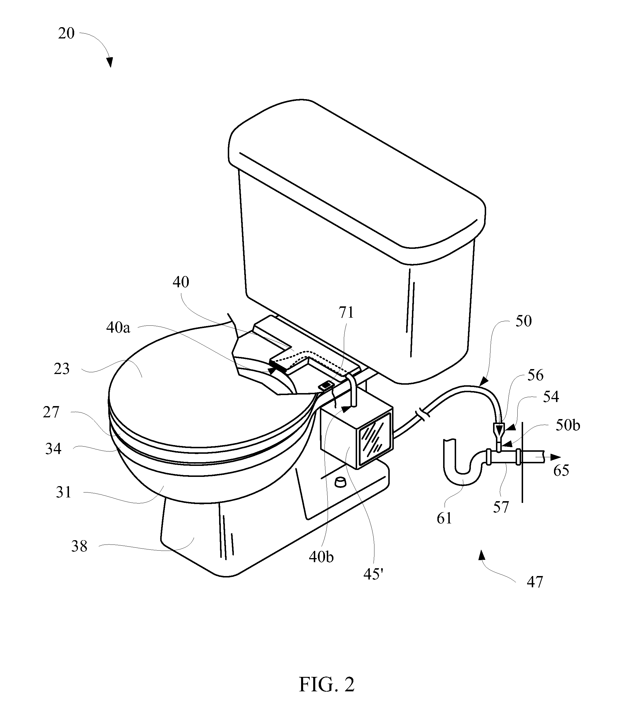
The present invention provides a toilet odor removal system that includes an intake conduit, a suction device, an exhaust conduit, and a power source. The intake conduit may be connected to a toilet bowl and the suction device may be connected to the intake conduit. The suction device may have a check valve to prevent air from escaping back through the conduit. The exhaust conduit may also have a check valve to prevent air from escaping back through the conduit. The toilet bowl may have a sensor to detect when a person is sitting on the toilet seat and a power supply may be attached to the suction device. The toilet seat can also have an intake conduit attached to it or formed integrally with it. The kit may also include a toilet seat lid with a sensor, a power supply, a sub-toilet seat, and / or an air exhaust conduit in the toilet bowl. The air intake conduit may be connected to the toilet bowl and the air exhaust conduit may be connected to a sink drain. The invention helps to remove toilet odors from the environment.

Problems solved by technology

Toilet odors can be an unpleasant and embarrassing problem.
Numerous solutions have been proposed to solve toilet odor problems, such as ceiling fans (which are inefficient because they evacuate not only the odorous air, but also the surrounding ambient air in the bathroom) and, more recently, toilets that evacuate malodorous air into the toilet sewer line.
Many of these approaches require significant and expensive modifications to the toilet, including drilling holes into the ceramic toilet.
Evacuation of malodorous air into the toilet sewer line involves significant technical problems, however, because inputting an airstream interferes with the flushing function of the toilet.

Method used


Image

  • Toilet odor removal system
  • Toilet odor removal system
  • Toilet odor removal system

Examples


Embodiment Construction

[0021]The following description includes specific details in order to provide a thorough understanding of the present toilet odor removal system. The skilled artisan will understand, however, that the methods described below can be practiced without employing these specific details, or that they can be used for purposes other than those described herein. Indeed, they can be modified and can be used in conjunction with products and techniques known to those of skill in the art in light of the present disclosure.

[0022]Reference in the specification to “one configuration” or “a configuration” means that a particular feature, structure, or characteristic described in connection with the configuration is included in at least one configuration. The appearances of the phrase “in one configuration” in various places in the specification are not necessarily all referring to the same configuration, and may not necessarily limit the inclusion of a particular element of the invention to a singl...


PUM


Abstract

A toilet odor removal system is described, wherein malodorous air in the bowl of the toilet is evacuated by suction through a tube and into the sink drainage system. The system may be used in the construction of new toilets, or may be easily adapted for sale as a kit to retrofit existing toilets. An intake tube may be located under the toilet seat, in connection with a suction device. The suction device may be coupled to an exhaust tube which connects to the sink drainage system below the p-trap of the sink The exhaust tube may also have a one-way check valve to prevent odors from the sewer system escaping into the ambient air of the bathroom. The odor removal system may also have an automatic means of turning on, such as a sensor or a pressure-activated switch.

Description

FIELD OF THE INVENTION[0001]The present invention relates to odor removal systems. More specifically, the present invention relates to an odor removal system for use with toilets.BACKGROUND[0002]Toilet odors can be an unpleasant and embarrassing problem. Numerous solutions have been proposed to solve toilet odor problems, such as ceiling fans (which are inefficient because they evacuate not only the odorous air, but also the surrounding ambient air in the bathroom) and, more recently, toilets that evacuate malodorous air into the toilet sewer line.[0003]Some solutions create a flange under the toilet to discharge the air directly into the sewer or devised other systems to discharge the air into the sewer below the toilet; some have proposed putting the air into the toilet flush line. Many of these approaches require significant and expensive modifications to the toilet, including drilling holes into the ceramic toilet. Evacuation of malodorous air into the toilet sewer line involves...

Claims


Application Information

Patent Timeline
Patent Type & Authority Applications(United States)
IPC IPC(8): E03D9/05
CPCA47K13/307E03D9/05
Inventor PRETE, ROY A.DETLOR, MILES J.
Owner PRETE ROY A
Learn More