Frame connection

a frame and connection technology, applied in the direction of furniture joining, sunshades, rod connections, etc., can solve the problems of visible fixings and detract from the appearance of the fram

Inactive Publication Date: 2013-10-17
U CLIK BARRIERS
View PDF9 Cites 30 Cited by
  • Summary
  • Abstract
  • Description
  • Claims
  • Application Information

AI Technical Summary

Benefits of technology

[0007]The present invention relates to a frame connection and, more particularly, to a frame connection for connecting members of a frame without visible fixings. The frame connection comprises a first elongate member having first and second channels, the first channel being in a first longitudinal side of the first elongate member and the second channel being in an opposed second longitudinal side of the first elongate member. The frame connection also comprises a second elongate member having first and second channels, the first channel being in a first longitudinal side of the second elongate member and the second channel being in an opposed second longitudinal side of the second elongate member. Further, the frame connection comprises a first connection member having a first end portion comprising a first planar member and a second end portion comprising a second planar member, each of the first and second end portions including one or more holes therein. Additionally, the frame connection comprises a second connection member having a first end portion comprising a first planar member and a second end portion comprising a second planar member, each of the first and second end portions including one or more holes therein The frame connection also comprises side cover members. Moreover, the first end portions of the first and second connection members are received in the first and second channels, respectively, of the first elongate member, the second end portions of the first and second connection members are received in the first and second channels, respectively, of the second elongate member, fasteners are received through the holes to secure the first and second connection members to the first and second elongate members, and the side cover members are then secured across the first and second channels of the first and second elongate members.

Problems solved by technology

While such an arrangement is relatively simple to assemble, the corner connection can tend to become loose due to flexing of the extrusions in use, Further, this arrangement can result in visible fixings, which detracts from the appearance of the frame.

Method used


Image

  • Frame connection
  • Frame connection
  • Frame connection

Examples


third embodiment

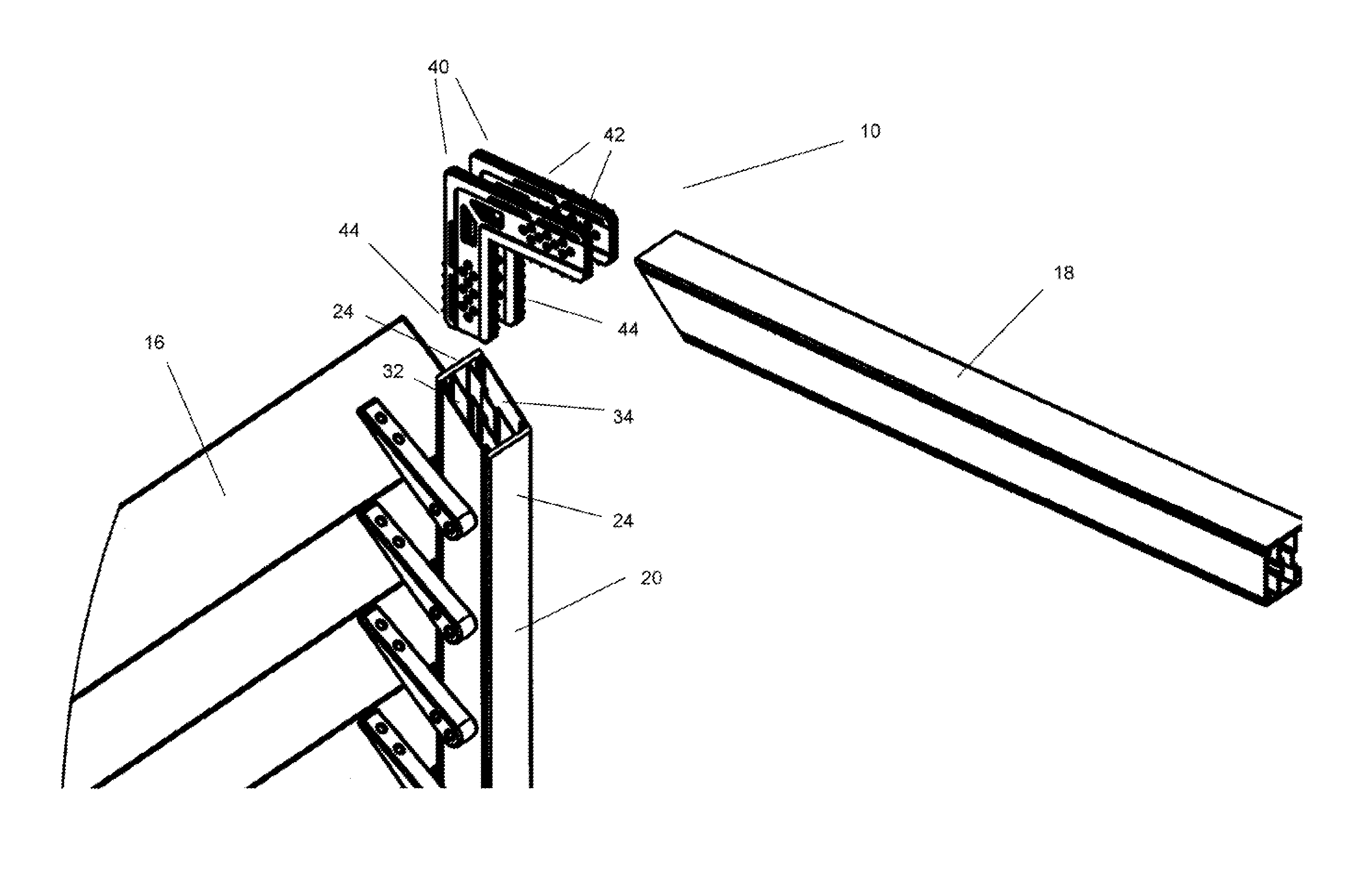
[0090]FIG. 13 illustrates a frame connection 10 in accordance with the present invention. The embodiment of FIG. 13 is similar to that of the embodiment of FIG. 9 and like reference numerals are used to denote like parts.

[0091]In the embodiment of FIG. 13, the first and second connection members 40 are fixed together. A connection body 62 is provided such that the connection body 62 connects a portion of the first connection member 40 between the first and second ends thereof to the second connection member 40 between the first and second ends thereof.

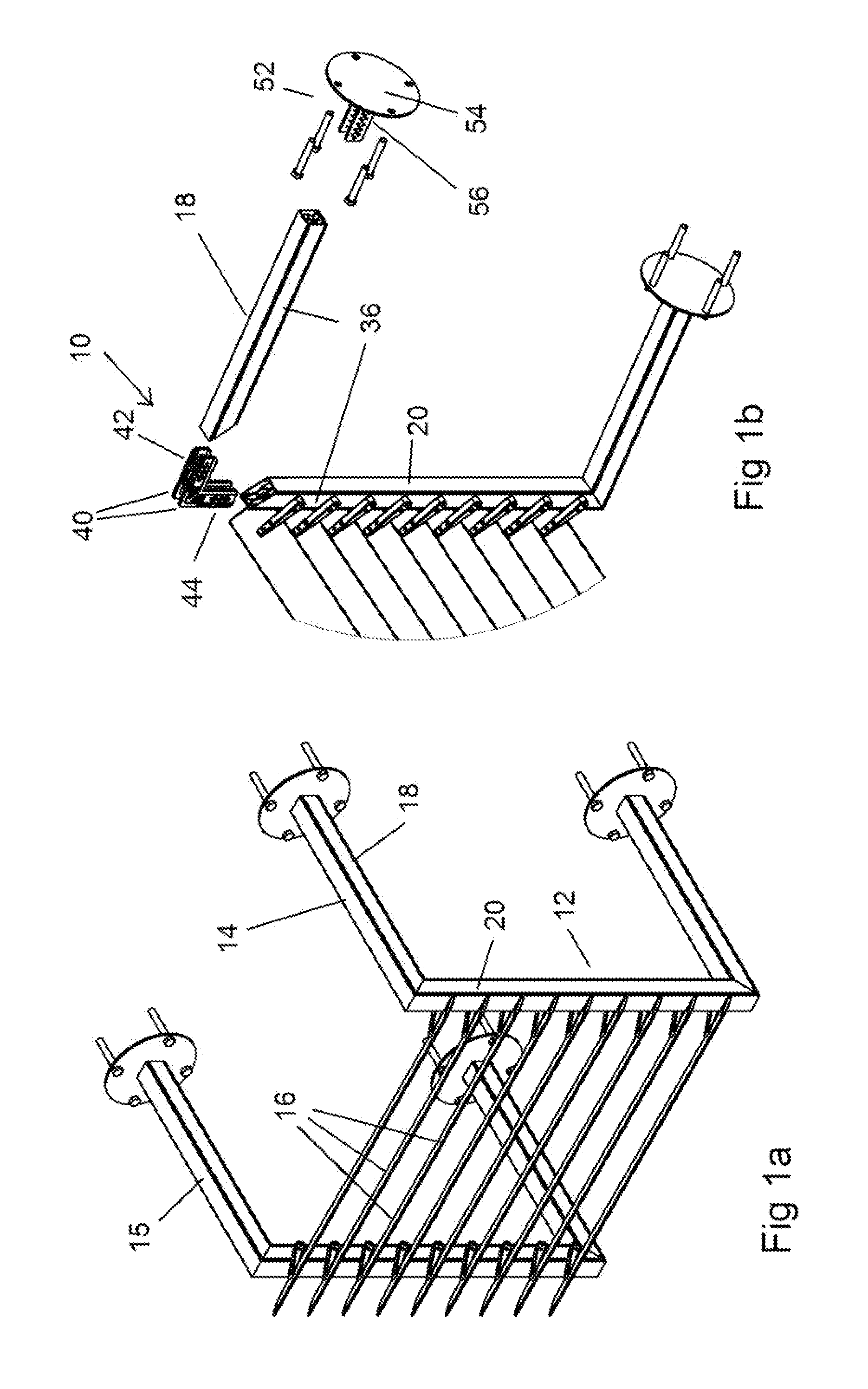
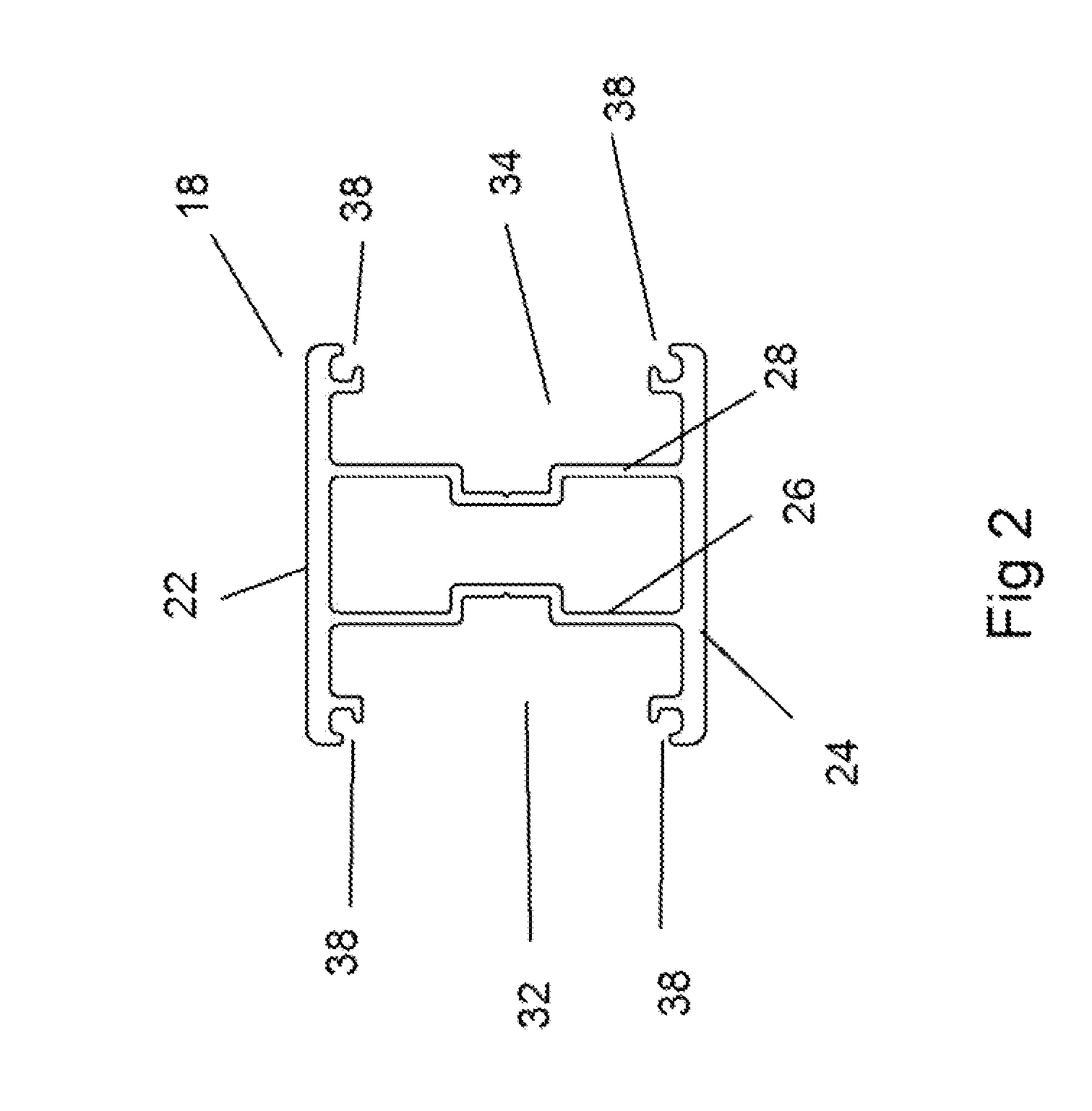
[0092]The side cover members 36 in this embodiment are connected by a curved top wall 37 such that a single cover unit 39 is provided for covering the first and second channels 32 and 34 and extending across the first end wall 22, The connection body 62 is provided with a cross sectional shape the same as that of the cover unit 39 such that a join having a consistent cross section throughout is created. The first and second elongate me...

fourth embodiment

[0095]FIG. 15 shows a frame connection 10 in accordance with the present invention. The embodiment of FIG. 15 is similar to that of the embodiment of FIG. 13 and like reference numerals are used to denote like parts.

[0096]In the embodiment of FIG. 15, the first and second connection members 40 are fixed together and a connection body 62 is provided such that the connection body 62 connects a portion of the first connection member 40 between the first and second ends 42 and 43 thereof to the second connection member 40 between the first and second ends 42 and 43 thereof.

[0097]The connection body 62, however, is provided with third end portions 45 extending in a direction perpendicular to both the first and second end portions 42 and 44. The first and second end portions 42 and 43 are provided, to connect the first elongate member 18 to the second elongate member 20 in the same manner as the second embodiment. The third end portions 45 are provided to connect to a third elongate membe...

fifth embodiment

[0098]FIG. 16 shows a frame connection 10 in accordance with the present invention. The embodiment of FIG. 16 is similar to that of the embodiment of FIG. 15 and like reference numerals are used to denote like parts.


PUM


Abstract

Described is a frame connection for connecting members of a frame without visible fixings. The frame connection comprises first and second elongate members, each having first and second channels. First and second connection members are provided, each having a first end portion comprising a first planar member and a second end portion comprising a second planar member. The end portions each include one or more holes therein. The first end portions of the first and second connection members are received in the first and second channels, respectively, of the first elongate member, and the second end portions are received in the first and second channels, respectively, of the second elongate member. Fasteners are received through the holes to secure the first and second connection members to the first and second elongate members and side cover members are then secured across the first and second channels.

Description

BACKGROUND OF THE INVENTION[0001](1) Field of Invention[0002]The present invention relates to a frame connection and, more particularly, to a frame connection for connecting members of a frame without visible fixings.[0003](2) Description of Related Art[0004]Many structures such as fence panels, screening panels, balustrades, and railings comprise an external frame supporting a plurality of cross members. The members forming the frame generally comprise extrusions that are cut at 45 degrees at the ends and secured to form the frame.[0005]A common method of joining the ends of the extrusions is to insert a single angle piece into the end of each of the extrusions and screw through the sides of the extrusions into the angle piece to hold the extrusions together. While such an arrangement is relatively simple to assemble, the corner connection can tend to become loose due to flexing of the extrusions in use, Further, this arrangement can result in visible fixings, which detracts from t...

Claims


Application Information

Patent Timeline
Patent Type & Authority Applications(United States)
IPC IPC(8): F16B7/00
CPCF16B7/00E06B3/9645E06B3/9682E06B3/9688E04F11/1836E06B7/082E06B7/086E04H17/1417E04F2011/1821E04F10/08E04F11/1814E04F11/1817E04F11/1834Y10T403/55F16B2200/67
Inventor HAYTER, DARRENKHOURY, EDWARD JOSEPH
Owner U CLIK BARRIERS
Why Eureka
Try Eureka