Cardiac activation time detection

a detection time and cardiac activation technology, applied in the field of signal analysis, can solve problems such as difficulty in accurate analysis of signals

Active Publication Date: 2013-10-24
BIOSENSE WEBSTER (ISRAEL) LTD
View PDF4 Cites 29 Cited by
  • Summary
  • Abstract
  • Description
  • Claims
  • Application Information

AI Technical Summary

Problems solved by technology

The signals typically have a relatively low level, of the order of millivolts, so that accurate analysis of the signals may be difficult.

Method used


Image

  • Cardiac activation time detection
  • Cardiac activation time detection
  • Cardiac activation time detection

Examples


Embodiment Construction

Overview

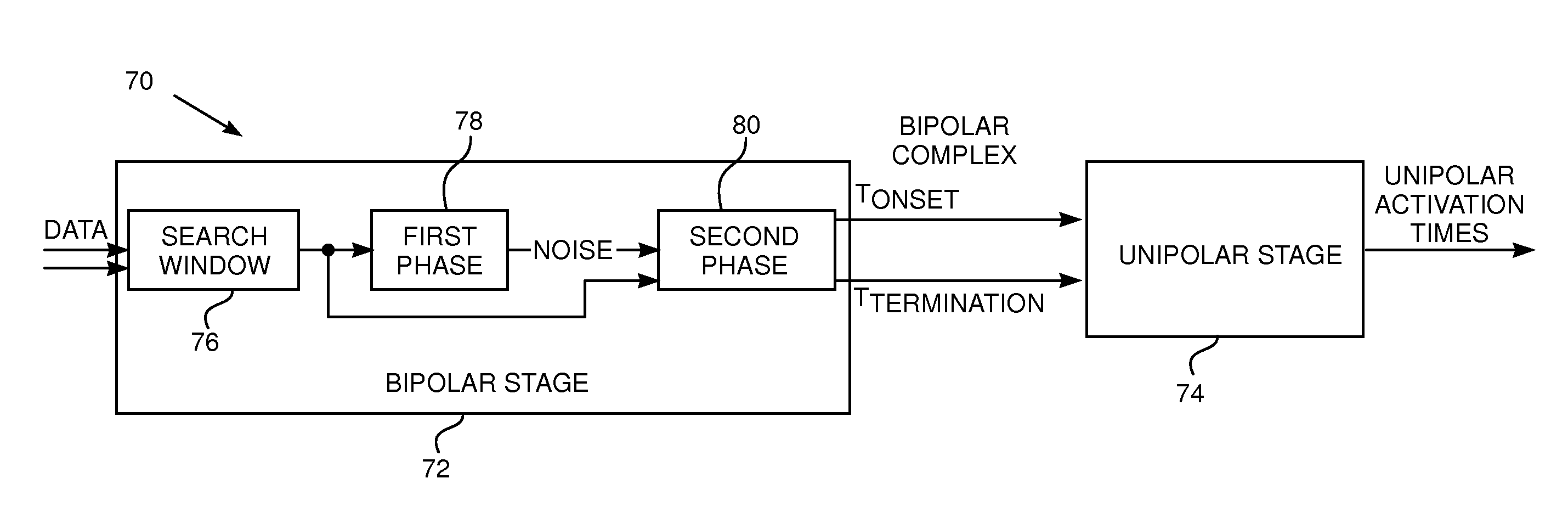
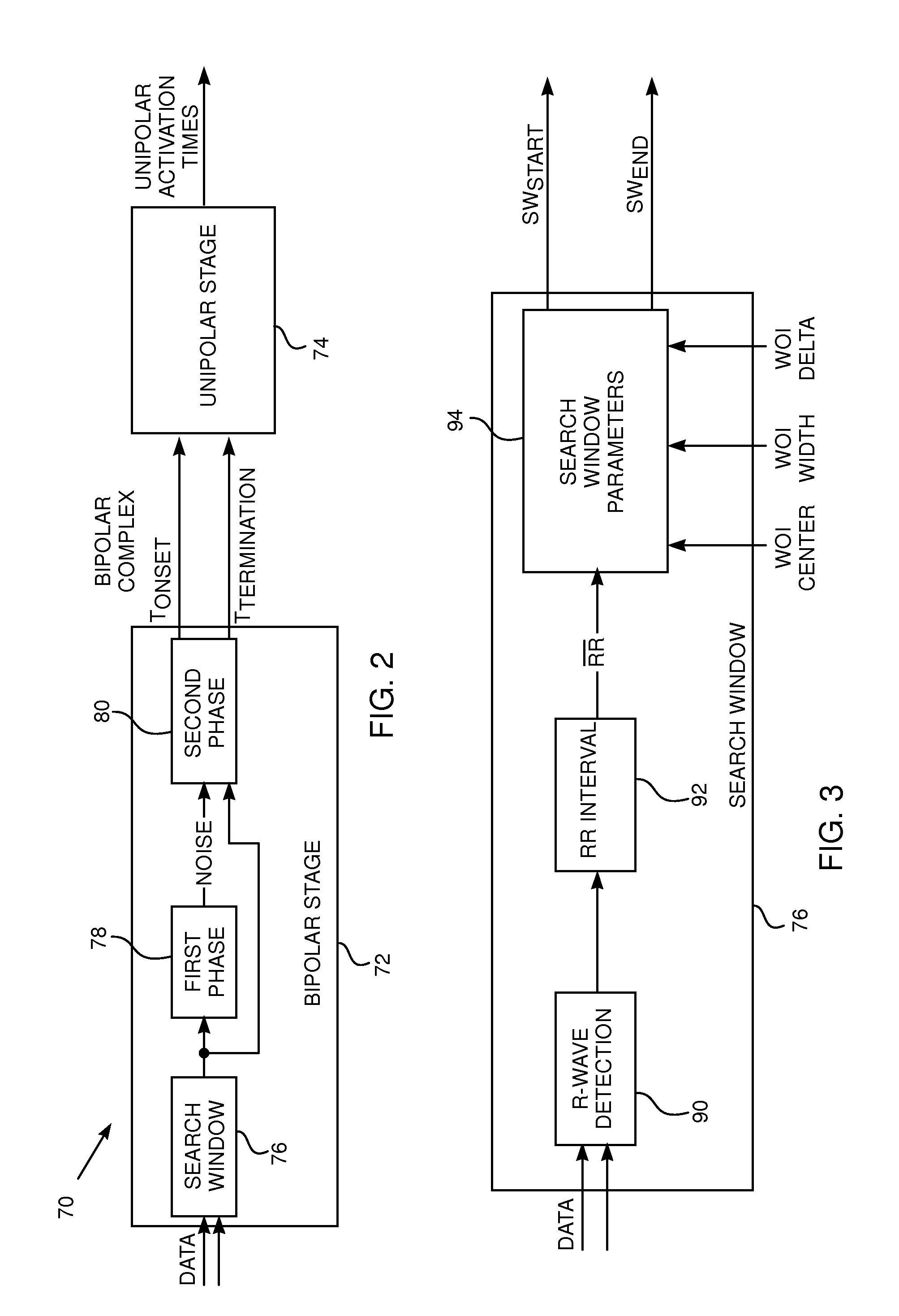
[0040]An embodiment of the present invention provides a method for characterizing an electrocardiogram, by processing electrocardiogram data in two stages. The data is in the form of two unipolar signals from two different locations in the heart, and the characterization is able to determine activation times of locations in the heart providing the data.

[0041]In a first stage of the process, the data is analyzed as a bipolar signal, to determine time instances of the signal that delineate a bipolar complex within signal. In a second stage of the process, the time instances are used as bounds within which each of the unipolar signals may be separately analyzed.

[0042]In order to determine the activation times of the different locations, a first derivative of each of the unipolar signals is evaluated. The time at which the first derivative is a minimum is assumed to be an onset activation time, i.e., the time at which tissue generating the unipolar signal begins to activate. The...


PUM


Abstract

A method for characterizing an electrocardiogram, including receiving a first unipolar signal from a first location of a heart and a second unipolar signal from a second location of the heart. The method further includes generating a bipolar signal from the first and second unipolar signals, and analyzing the bipolar signal to delineate a time period during which the first and second locations generate a bipolar complex. The method also includes analyzing the first unipolar signal within the time period to determine an activation time of the first location.

Description

FIELD OF THE INVENTION[0001]The present invention relates generally to signal analysis, and specifically to analysis of signals generated by a beating heart.BACKGROUND OF THE INVENTION[0002]One of the methods for characterizing cardiac activity relies on analyzing electrical signals generated by a heart as the heart beats. The signals typically have a relatively low level, of the order of millivolts, so that accurate analysis of the signals may be difficult. Notwithstanding the difficulties, accurate analysis can lead to improved characterization of heart activity, including determination of regions of the heart which may be defective.[0003]Documents incorporated by reference in the present patent application are to be considered an integral part of the application except that to the extent any terms are defined in these incorporated documents in a manner that conflicts with the definitions made explicitly or implicitly in the present specification, only the definitions in the prese...

Claims


Application Information

Patent Timeline
Patent Type & Authority Applications(United States)
IPC IPC(8): A61B5/0402
CPCA61B5/7203A61B5/7239A61B5/316A61B5/283A61B5/287A61B5/349
Inventor EL HADDAD, MILAD ABBASHAYAM, GALBAR-TAL, MEIRHOUBEN, RICHARD PETRUS MARIADUYTSCHAEVER, MATTIAS FRANCIS
Owner BIOSENSE WEBSTER (ISRAEL) LTD
Why Eureka
Try Eureka