Automatic bipolar signal switching

a bipolar signal and automatic technology, applied in the direction of electronic switching, pulse technique, altering/correcting variation law, etc., can solve the problems of time-consuming and complex

Active Publication Date: 2015-02-24
BAKER HUGHES INC
View PDF10 Cites 7 Cited by
  • Summary
  • Abstract
  • Description
  • Claims
  • Application Information

AI Technical Summary

Benefits of technology

[0005]One or more specific embodiments of the present invention will be described below. In an effort to provide a concise description of these embodiments, all features of an actual implementation may not be described in the specification. It should be appreciated that in the development of any such actual implementation, as in any engineering or design project, numerous implementation-specific decisions must be made to achieve the developers' specific goals, such as compliance with system-related and business-related constraints, which may vary from one implementation to another. Moreover, it should be appreciated that such a development effort might be complex and time consuming, but would nevertheless be a routine undertaking of design, fabrication, and manufacture for those of ordinary skill having the benefit of this disclosure.

Problems solved by technology

Moreover, it should be appreciated that such a development effort might be complex and time consuming, but would nevertheless be a routine undertaking of design, fabrication, and manufacture for those of ordinary skill having the benefit of this disclosure.

Method used


Image

  • Automatic bipolar signal switching
  • Automatic bipolar signal switching
  • Automatic bipolar signal switching

Examples


Embodiment Construction

[0015]One or more specific embodiments of the present invention will be described below. In an effort to provide a concise description of these embodiments, all features of an actual implementation may not be described in the specification. It should be appreciated that in the development of any such actual implementation, as in any engineering or design project, numerous implementation-specific decisions must be made to achieve the developers' specific goals, such as compliance with system-related and business-related constraints, which may vary from one implementation to another. Moreover, it should be appreciated that such a development effort might be complex and time consuming, but would nevertheless be a routine undertaking of design, fabrication, and manufacture for those of ordinary skill having the benefit of this disclosure.

[0016]When introducing elements of various embodiments of the present invention, the articles “a,”“an,”“the,” and “said” are intended to mean that ther...


PUM


Abstract

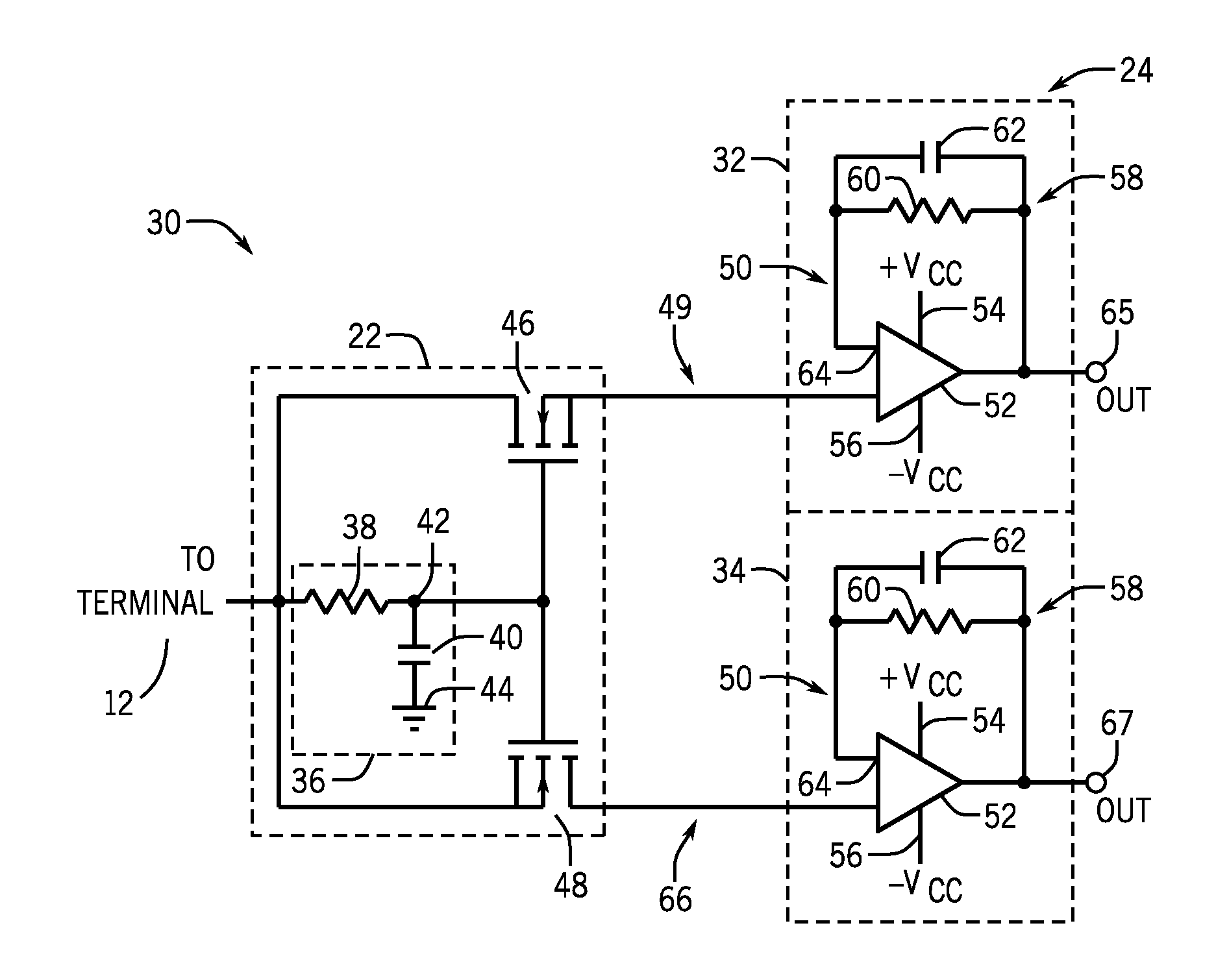
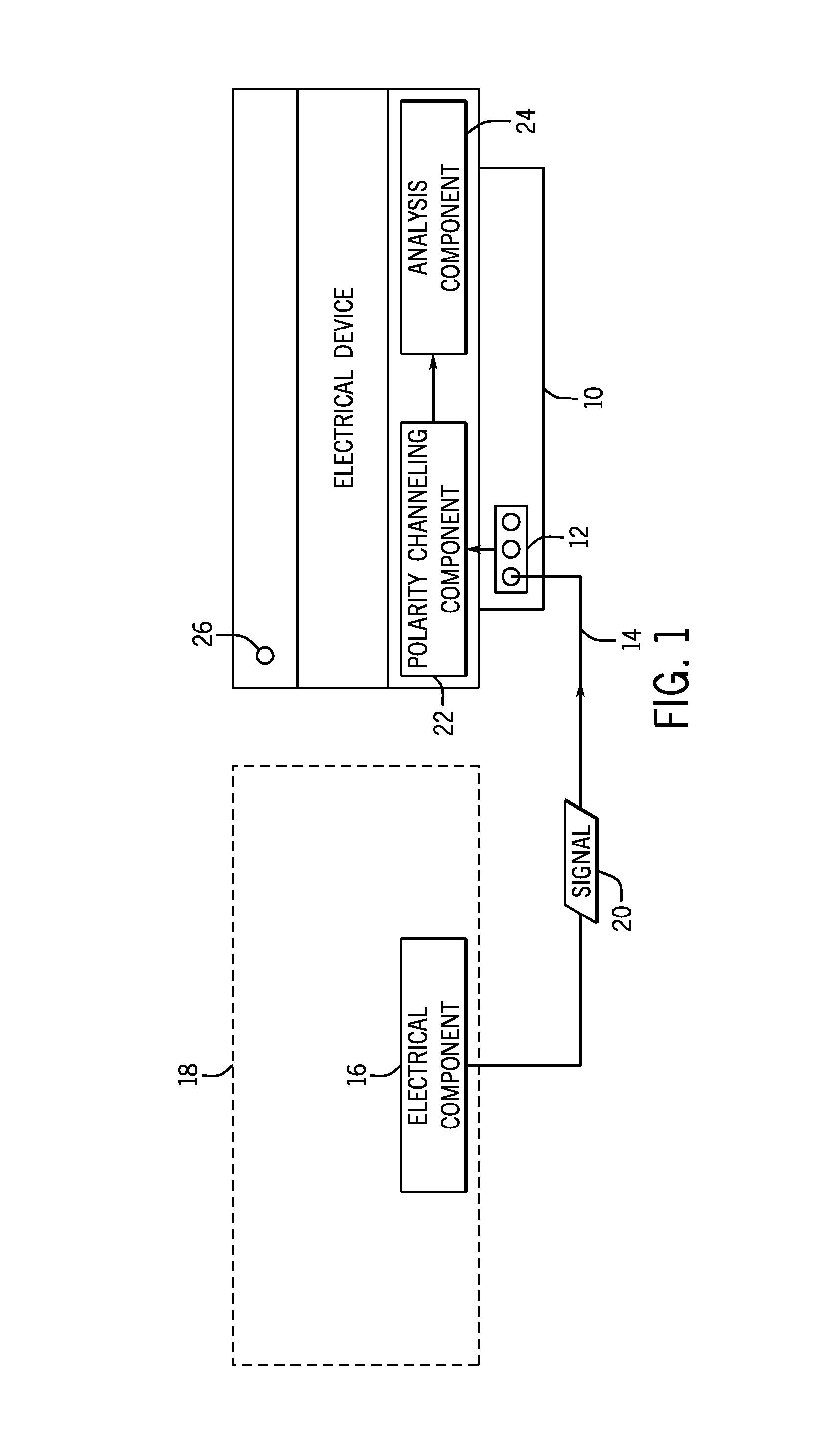
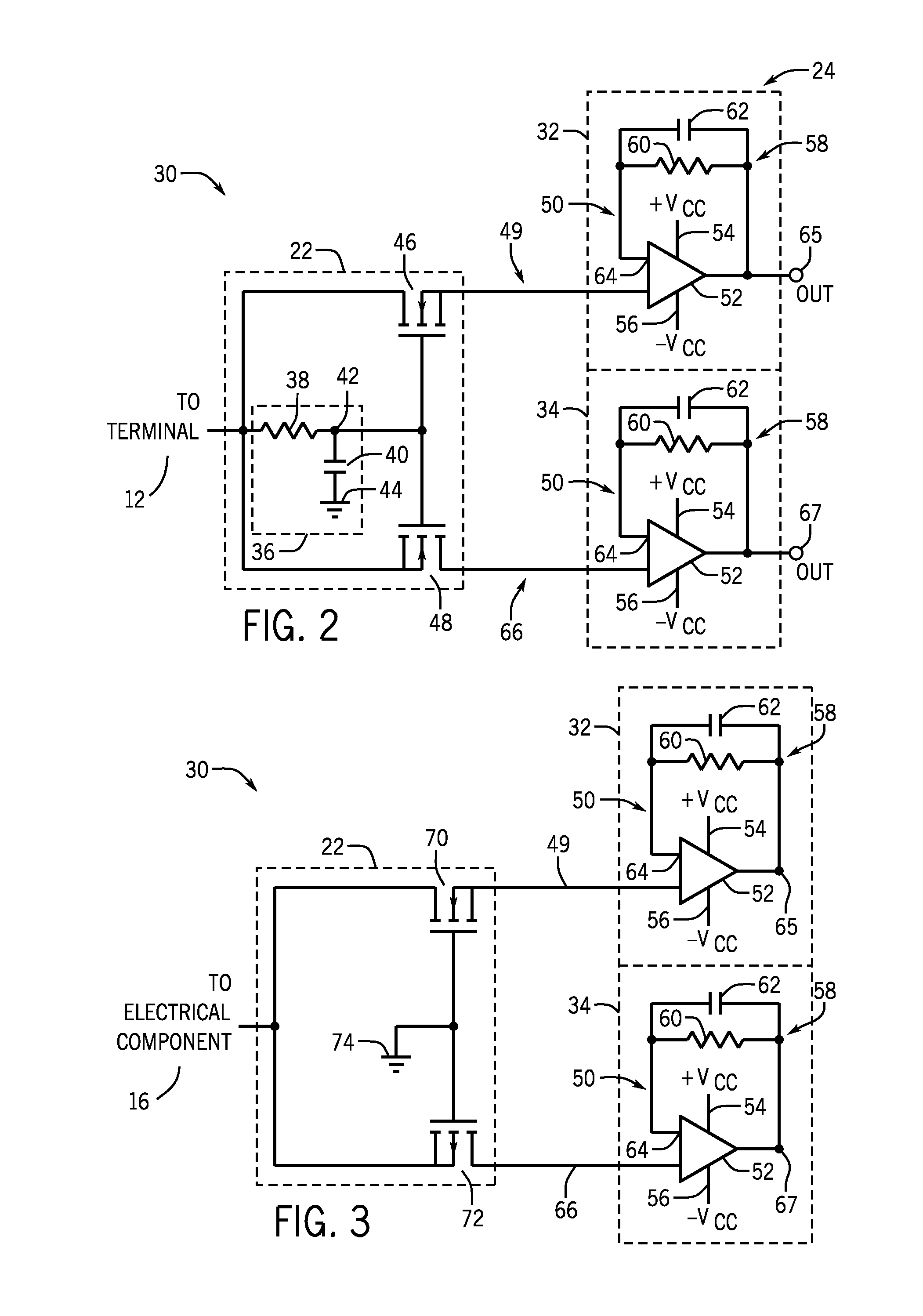
A system is provided that includes an input node configured to receive a signal indicative of sensor data. The system also includes a first transistor configured to route the signal to a positive channel when a polarity of the signal is positive. Moreover, the system includes a second transistor configured to route the signal to a negative channel when a polarity of the signal is negative. Additionally, the system includes the positive channel coupled to the first transistor configured to route the signal to an analysis component. Furthermore, the system includes the negative channel coupled to the second transistor and configured to route the signal to the analysis component.

Description

BACKGROUND[0001]The subject matter disclosed herein generally relates to signal routing to an electrical device based on a polarity of the signal.[0002]To enable an electrical device (e.g., instrumentation device) to couple to a variety of components (e.g., transducers) that may have either a positive polarity (e.g., AC signal with +12 DC offset) or a negative polarity (e.g., AC signal with a −12 DC offset), multiple terminals in the electrical device with a dedicated terminal for expected voltages may be utilized. However, such devices include unused terminals (depending on the implementation of the device) to be included in the device, thereby increasing production costs of the device inefficiently. Other electrical devices may instead include an analog multiplexer (MUX) circuit coupled between a terminal and internal circuitry to allow a device to be coupled to a variety of components. However, these devices are often vulnerable to damage due to a susceptibility of the MUX to dam...

Claims


Application Information

Patent Timeline
Patent Type & Authority Patents(United States)
IPC IPC(8): H03K17/00H03K17/16
CPCH03K17/16H03K17/161G01D3/024H03K5/082
Inventor ABAWI, DANIEL ZAHIROYLANCE, JAMES MERRILL
Owner BAKER HUGHES INC
Why Eureka
Try Eureka