Multi-channel network monitoring apparatus, signal replicating device, and systems including such apparatus and devices, and enclosure for multi-processor equipment

a network monitoring and multi-channel technology, applied in the field of telecom networks, can solve the problems of multiplication of losses, inability to consider the approach without due attention to the optical power budget of the bearer, and the quantity of data that needs to be processed for the monitoring of ip traffi

Inactive Publication Date: 2005-08-02
VIAVI SOLUTIONS INC
View PDF19 Cites 68 Cited by
  • Summary
  • Abstract
  • Description
  • Claims
  • Application Information

AI Technical Summary

Problems solved by technology

A problem arises, however, in the quantity of data that needs to be processed for the monitoring of IP traffic.
However, this approach cannot be considered without due attention to the optical power budget of the bearer, as the optical splitters are lossy devices.
With available instrumentation, this implies a multiplication of the losses, and also disruption to the bearers as each new splitter is installed.
Issues of upgrading the transmitter and / or receiver arise as losses mount up.
Further analysis shows that the majority of operational hours lost are caused by planned and unplanned maintenance, while hardware failures have a relatively minor effect.
Accordingly, increasing the redundancy of disk drives, power supplies and the like, although psychologically comforting, can do relatively little to improve system availability.
Manufacturers have alternatively built diagnostic capability into the network equipment itself, but each perceives the problems differently, leading to a lack of uniformity, and actual monitoring problems, as opposed to perceived problems, may not be addressed.
Such standards impose limitations such as connectivity and physical dimensions upon equipment and, consequently, on cooling requirements and aisle spacing of network rack equipment.
Even with Intel Pentium™ or similar processors, however, such arrangements do not currently accommodate the computing power needed for the capture and analysis of broadband packet data.
Aside from the volume of data to be handled, conventional chassis for housing such modules do not also support probe architectures of the type currently desired, both in terms of processing capability and also to the extent that their dimensions do not suit the layout of telecommunication equipment rooms such as may be designed to NEBS allowing them to co-reside with network equipment.
It is noted that known chassis designs and backplanes do not provide for several channels of signals to be monitored by independent processing sub-systems within the same chassis, especially when each monitoring unit processor in fact requires more than one card slot for its implementation.

Method used


Image

  • Multi-channel network monitoring apparatus, signal replicating device, and systems including such apparatus and devices, and enclosure for multi-processor equipment
  • Multi-channel network monitoring apparatus, signal replicating device, and systems including such apparatus and devices, and enclosure for multi-processor equipment
  • Multi-channel network monitoring apparatus, signal replicating device, and systems including such apparatus and devices, and enclosure for multi-processor equipment

Examples


Embodiment Construction

Background

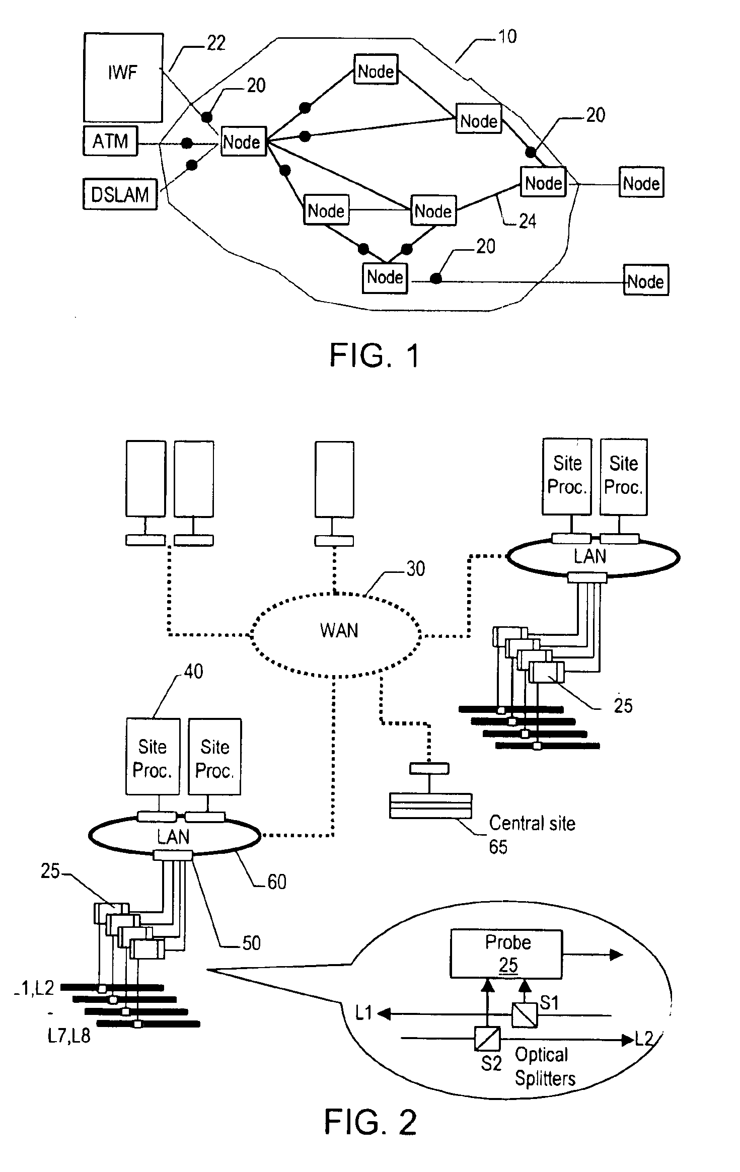
[0104]FIG. 1 shows a model of a telecommunication network 10 based on asynchronous transfer mode (ATM) bearers. Possible monitoring points on various bearers in the network are shown at 20 and elsewhere. Each bearer is generally an optical fibre carrying packetised data with both routing information and data “payload” travelling in the same data stream. Here “bearer” is used to mean the physical media that carries the data and is distinct from a “link”, which in this context is defined to mean a logical stream of data. Many links of data may be multiplexed onto a single bearer. These definitions are provided for consistency in the present description, however, and should not be taken to imply any limitation of the applicability of the techniques disclosed, or on the scope of the invention defined in the appended claims. Those skilled in the art will sometimes use the term “channel” to refer to a link (as defined), or “channel” may be used to refer to one of a number of vir...


PUM


Abstract

A multi-channel network monitoring apparatus has input connectors for network signals to be monitored and four channel processors in a rack-mountable chassis/enclosure for receiving and processing a respective pair of incoming signals to produce monitoring results. Each processor operates independently of the others and is replaceable without interrupting their operation. LAN connectors enable onward communication of the monitoring results. A cross-point switch routes each incoming signal to a selected processor and can re-route a channel to another processor in the event of processor outage. Each processor has a self-contained sub-system of processing modules interconnected via a CPU-peripheral interface in a backplane, which provides a separate peripheral interface for each processor. The backplane provides locations for processors to lie horizontally across a major portion of the backplane area facing the front of the enclosure, and a location for an interface module over a minor portion of that area facing the rear, so as to provide external connectors at the rear of the enclosure. A power supply module is positioned over another portion of the backplane area, on the same side as the interface module. The location of the power supply module behind the backplane saves height and/or width in the rack.

Description

INTRODUCTION[0001]The invention relates to telecommunications networks, and in particular to apparatus and systems for monitoring traffic in broadband networks.[0002]In telecommunication networks, network element connectivity can be achieved using optical fibre bearers to carry data and voice traffic.[0003]Data traffic on public telecommunication networks is expected to exceed voice traffic with Internet Protocol (IP) emerging as one data networking standard, in conjunction with Asynchronous Transfer Mode (ATM) systems. Voice over IP is also becoming an important application for many Internet service providers with IP switches connecting IP networks to the public telephony network (PSTN). IP can be carried over a Sonet transport layer, either with or without ATM. In order to inter-operate with the PSTN, IP switches are also capable of inter-working with SS7, the common signalling system for telecommunications networks, as defined by the International Telecommunications Union (ITU) s...

Claims


Application Information

Patent Timeline
Patent Type & Authority Patents(United States)
IPC IPC(8): G06F11/00H04L12/26H04L12/66
CPCH04L12/2602H04L43/00H04L49/555
Inventor REYNOLDS, ALASTAIRCARSON, DOUGLAS JOHNLUNN, GEORGE CROWTHERMACISAAC, WILLIAM ROSS
Owner VIAVI SOLUTIONS INC
Why Eureka
Try Eureka