Optical transmitter and optical signal generating method

An optical transmitter and optical signal technology, which is applied in the field of optical communication, can solve the problems of difficult integration, high cost of the transmitter, and large volume, and achieve good stability and reliability, lower cost, and lower insertion loss.

Active Publication Date: 2009-09-09
HUAWEI TECH CO LTD +1
View PDF0 Cites 8 Cited by
  • Summary
  • Abstract
  • Description
  • Claims
  • Application Information

AI Technical Summary

Problems solved by technology

[0005] The transmitter uses two modulators to generate CSRZ optical pulses and DQPSK signals respectively, that is, two-level modulation is required, so the cost of the transmitter is high, the volume is large, and it is not easy to integrate
At the same time, the transmitter uses discrete optical devices, and the driving signals of the two modulators need to be strictly adjusted to achieve synchronization, which increases the insertion loss of the entire transmitter
[0006] In addition, the traditional Manchester pattern is realized through the XOR operation between the clock signal and the data signal (using an XOR gate), but the XOR gate is an active device and needs to be driven by an external voltage, resulting in a relatively high cost of the transmitter. high

Method used


Image

  • Optical transmitter and optical signal generating method
  • Optical transmitter and optical signal generating method
  • Optical transmitter and optical signal generating method

Examples


Embodiment 1

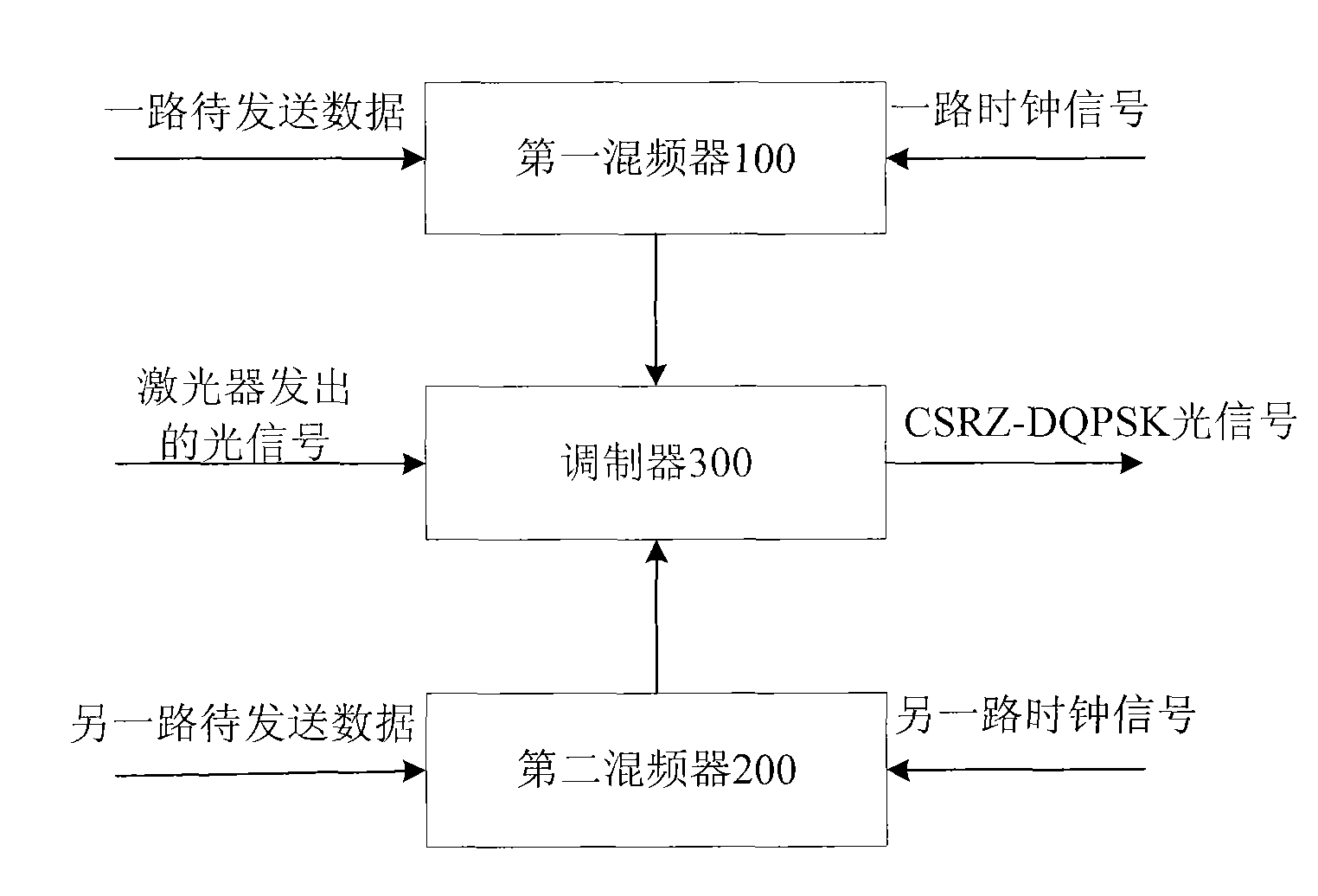
[0038] see figure 2 , this embodiment provides an optical transmitter, including:

[0039] The first mixer 100 is used to receive one channel of data to be sent and one channel of clock signal, the frequency value of the channel of clock signal is half of the rate value of one channel of data to be transmitted, and mix the channel of data to be transmitted with one channel of clock signal , generate the first return-to-zero code bipolar signal, and output the first return-to-zero code bipolar signal;

[0040] The second mixer 200 receives another road to be sent data and another road clock signal, the frequency value of the other road clock signal is half of the rate value of the other road data to be sent, and compares the other road data to be sent with the other road clock signal Frequency mixing to generate the second return-to-zero code bipolar signal, and output the second return-to-zero code bipolar signal;

[0041]The modulator 300 is used to receive the optical sig...

Embodiment 2

[0056] Referring to Figure 7, this embodiment provides an optical transmitter, including:

[0057] The mixer 600 is used to receive the data to be sent and the sinusoidal clock signal, wherein the frequency value of the sinusoidal clock signal is the same as the rate value of the data to be sent, and the phase of the sinusoidal clock signal is adjusted so that the phase of the sinusoidal clock signal is consistent with the data to be sent Synchronization, mixing the data to be sent with the phase-adjusted sinusoidal clock signal to generate Manchester code and output Manchester code;

[0058] The modulator 700 is configured to receive the optical signal and the Manchester code output by the mixer 600, and modulate the Manchester code onto the optical signal under the action of a bias voltage to generate a Manchester optical signal.

[0059] Wherein, the data to be sent is the original data; in order to increase the driving capability of the signal to the modulator, an electric...

Embodiment 3

[0064] see Figure 10 , the present embodiment provides a method for generating an optical signal, including:

[0065] Step 801: Divide the data to be sent into two paths;

[0066] Step 802: mixing the two channels of data to be sent with the two channels of clock signals respectively to generate two channels of return-to-zero code bipolar signals; wherein, the frequency value of the clock signal is half of the rate value of the data to be transmitted;

[0067] Step 803: Modulate the two return-to-zero code bipolar signals respectively, respectively modulate the two return-to-zero code bipolar signals onto the two optical signals, and combine the modulated two optical signals to generate CSRZ- DQPSK optical signal.

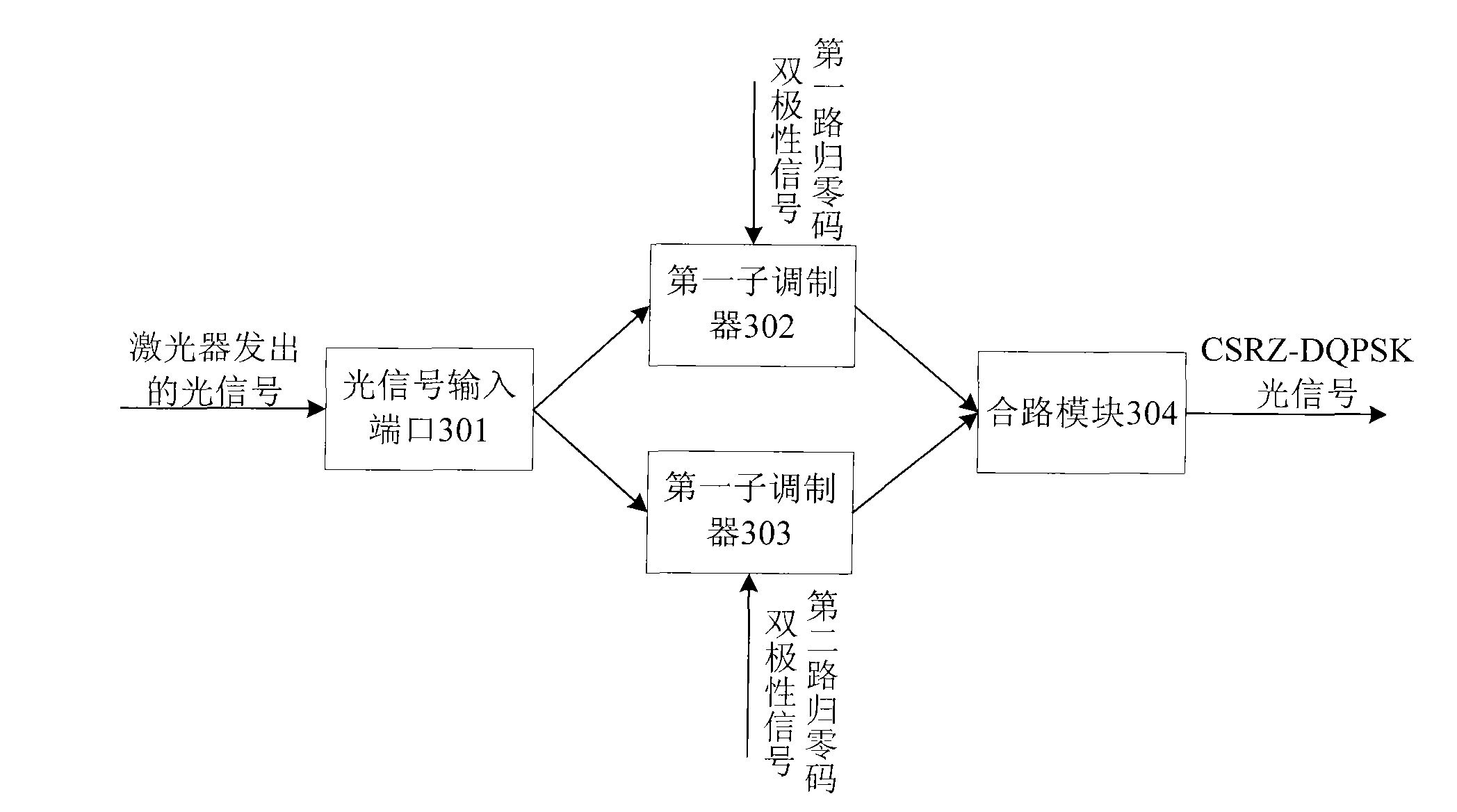
[0068] Wherein, step 803 can specifically be passed image 3 The provided DQPSK modulator realizes the modulation of the signal, and the modulation method is briefly described as follows:

[0069] Under the action of the first bias voltage, one path of return-...


PUM


Abstract

The invention discloses an optical transmitter and an optical signal generating method, which belong to the field of optical communication. The optical transmitter comprises a first frequency mixer, a second frequency mixer and a modulator; or the optical transmitter comprises a frequency mixer and the modulator. The method comprises the following steps: dividing the data to be transmitted into two paths which are mixed with two paths of clock signals respectively to generate two paths of return-to-zero bipolar signals; and respectively modulating the bipolar signals to generate a CSRZ-DQPSK optical signal. Or the method comprises the following steps: receiving the data to be transmitted and a sine clock signal, adjusting the phase of the sine clock signal to synchronize the phase of the sine clock signal and the data to be transmitted, and carrying out the frequency mixing to generate a Manchester code; and modulating the Manchester code to the optical signal to generate a Manchester optical signal. The method carries out the frequency mixing of the data to be transmitted and the clock signal and drives the modulator through the signal after frequency mixing to generate the CSRZ-DQPSK optical signal or the Manchester optical signal, thereby reducing the cost of the optical transmitter.

Description

technical field [0001] The invention relates to the field of optical communication, in particular to an optical transmitter and a method for generating an optical signal. Background technique [0002] With the increase of communication capacity, especially the popularity of high-speed Ethernet and the development of multimedia services, people have put forward higher requirements for the existing optical fiber communication system. Long-distance, large-capacity wavelength division multiplexing (WDM, Wavelength Division Multiplexing ) system is becoming a research and commercial hotspot. At present, the 40Gb / s system has already started commercial use, and the ultra-high-speed transmission systems of 100Gb / s and 160Gb / s are receiving widespread attention in the industry. As the data rate increases, the performance of traditional transmission systems using amplitude modulation formats such as NRZ (Non Return-to-Zero) and Return-to-Zero (RZ, Return-to-Zero) is greatly affected...

Claims


Application Information

Patent Timeline
Patent Type & Authority Applications(China)
IPC IPC(8): H04B10/155H04B10/50H04B10/516H04B10/556
CPCH04B10/5165H04B10/505H04B10/5162H04B10/5561
Inventor 高俊明昌庆江苏翼凯陶智慧
Owner HUAWEI TECH CO LTD
Why Eureka
Try Eureka