

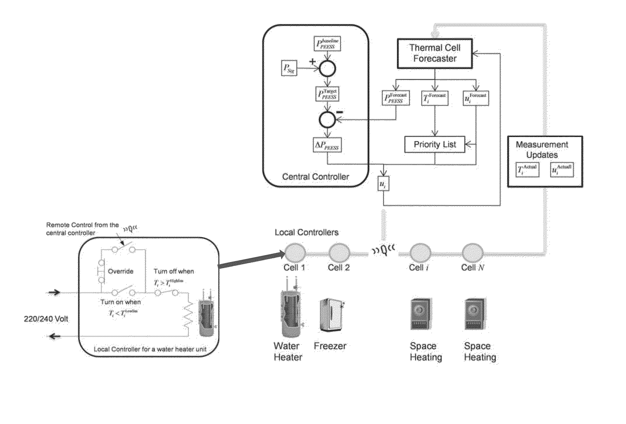
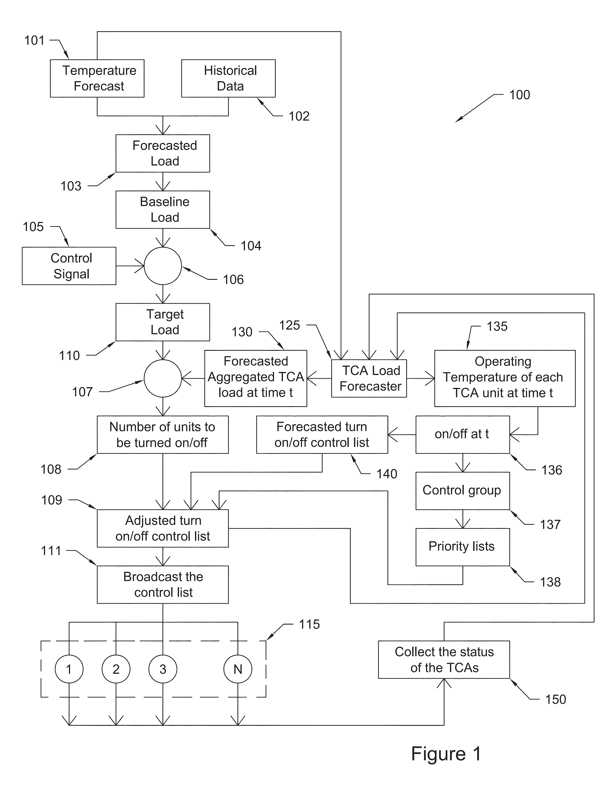
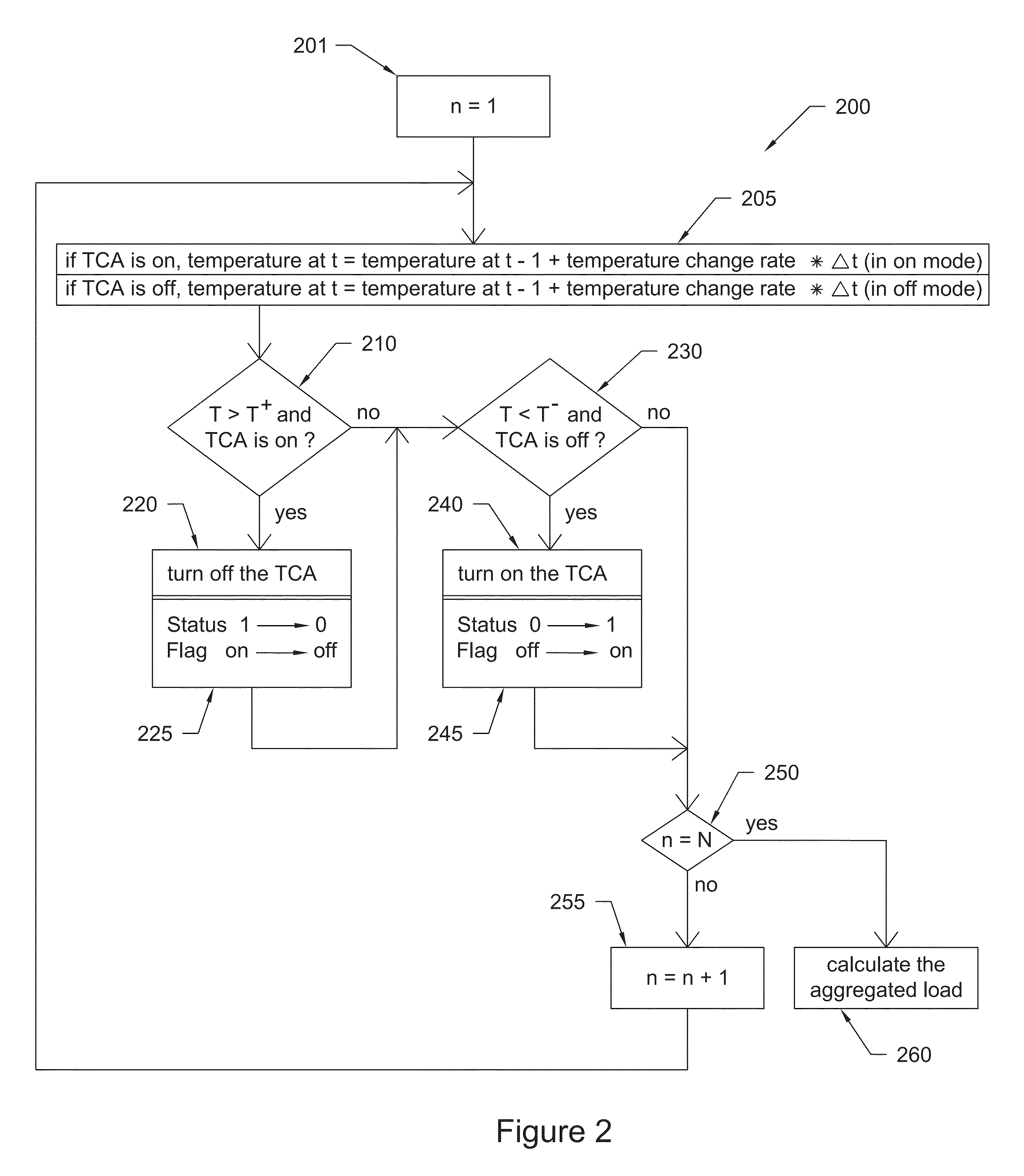
Controller for thermostatically controlled loads
- Summary
- Abstract
- Description
- Claims
- Application Information
AI Technical Summary
Benefits of technology
Problems solved by technology
Method used
Image

Examples
case b
ect Forecast Case
[0132]Two scenarios are simulated: Tdeadband=4° C. (Case B1) and Tdeadband=2° C. (Case B2). Simulation results shown in FIG. 18 through FIG. 20 demonstrated:[0133]The forecaster updates algorithm is effective. Because the forecaster located at the control center is only an approximation of the real HVAC unit, it will have prediction errors. In some cases, the forecast error may be significant, as shown in FIG. 18. However, if every 15 minutes, the error can be corrected by measurements collected from the AMI network, then the forecaster can still predict relatively well the state the HVAC unit is in.[0134]The simplified HVAC model adjusted by 15-minute meter data updates does not degrade the capability of the HVAC load to follow the control signal, as shown in FIG. 19A. The adverse impacts are that the number of switching will increase about 3-5 times a day, see FIG. 19B and room temperatures may overshoot for half a degree or so. This is because if the forecast is ...
case d
se Delay
[0138]This case is designed to test how much tolerance the control mechanism has for response delays from resources that are not only geographically far away from each other but also different in design. The delay may be caused by communication delays or other factors. To model the impact of the response delay on the load following capability of the aggregated HVAC load, three scenarios are modeled:[0139]Random response delay: within 2 minutes (Case D1)[0140]Random response delay: within 5 minutes (Case D2)[0141]95% chance to react immediately and 5% chance to have random response delay within 5 minutes (Case D3)
[0142]As shown in FIG. 21, among the eight cases simulated so far, the response delay has the biggest impact on percentage errors, PE, which are calculated by
PE=Pactual(i)-PcLF(i)PcLF(i)(10)
[0143]where Pactual is the actual HVAC power consumption for each case. To reduce this error, there are two options. First, if the communication system design can guarantee that a...
PUM
 Abstract
Description
Claims
Application Information