Louver display panel system for multi-story building

a display panel and multi-story technology, applied in the field of display panels, can solve the problems of presenting a structure that can be easily destroyed or damaged, form of advertising being blown off the building, and affecting the appearance of the building, so as to reduce the wind load

Inactive Publication Date: 2013-10-31
MELIC JOHN J
View PDF17 Cites 22 Cited by
  • Summary
  • Abstract
  • Description
  • Claims
  • Application Information

AI Technical Summary

Benefits of technology

[0010]Accordingly, in one of its aspects the invention provides a louver display panel system comprising one or more display panels for receiving advertising or other printed or graphic material thereon; one or more support members to secure said one or more display panels to a building or structure, said one or more display panels rotationally secured and mounted to said one or more support members and forming a louver structure; at least one louver movement control means, said louver movement control means maintaining said one or more display panels in a first position where they are in a plane generally parallel to the exterior face of the building or structure until a forwardly or rearwardly directed wind load applied to said one or more display panels exceeds a pre-determined value, after which said louver movement control means permits said one or more display panels to at least partially rotate toward a second position that is generally parallel to the direction of the wind to reduce the wind load borne by said one or more display panels, said louver movement control means returning said one or more display panels to said first position when the wind load drops below said pre-determined value.
[0011]In a further aspect the invention provides a louver display panel system comprising a generally rectangular display panel rotationally secured and mounted to a pair of support posts that are releasably securable to a building or structure, said display panel forming a louver structure; and a pair of louver movement control means associated with said display panel, each of said control means comprising a pair of pneumatic or hydraulic cylinders mounted end to end with their pistons extending in opposite directions and having one piston secured to one of said support posts and the other of said pistons secured to a bracket secured to said display panel, said pneumatic or hydraulic cylinders maintaining said display panel in a plane that is generally parallel to the exterior face of the building or structure until either a forwardly or rearwardly directed wind load is applied to said panel that exceeds a pre-determined value, after which said pneumatic or hydraulic cylinders permit said display panel to rotate to thereby reduce the wind load borne by said display panel, said pneumatic or hydraulic cylinders returning said display panel to its position where it is generally parallel to the exterior face of the building or structure when said wind load drops below said pre-determined value.

Problems solved by technology

The difficulty that construction companies and developers have traditionally faced is how to easily and economically display advertising from the building without interfering in its construction, and at the same time without presenting a structure that can be easily destroyed or damaged when exposed to high winds.
There is also a concern that any form of advertising could be blown off the building causing damage to property or injury to persons below.
Unfortunately, since the slits are usually cut into relatively flexible material they often open during times of relatively low wind, obscuring portions of the advertising printed on the banner.
If subjected to high winds the slits may not be of sufficient size to allow enough air to pass through the banner, which may result in either a ripping of the banner or the banner blowing completely off of the building structure.
As the weave becomes more open there is less material upon which to print advertising, making the ability for the display of sharp and crisp images rather limited.

Method used


Image

  • Louver display panel system for multi-story building
  • Louver display panel system for multi-story building
  • Louver display panel system for multi-story building

Examples


Embodiment Construction

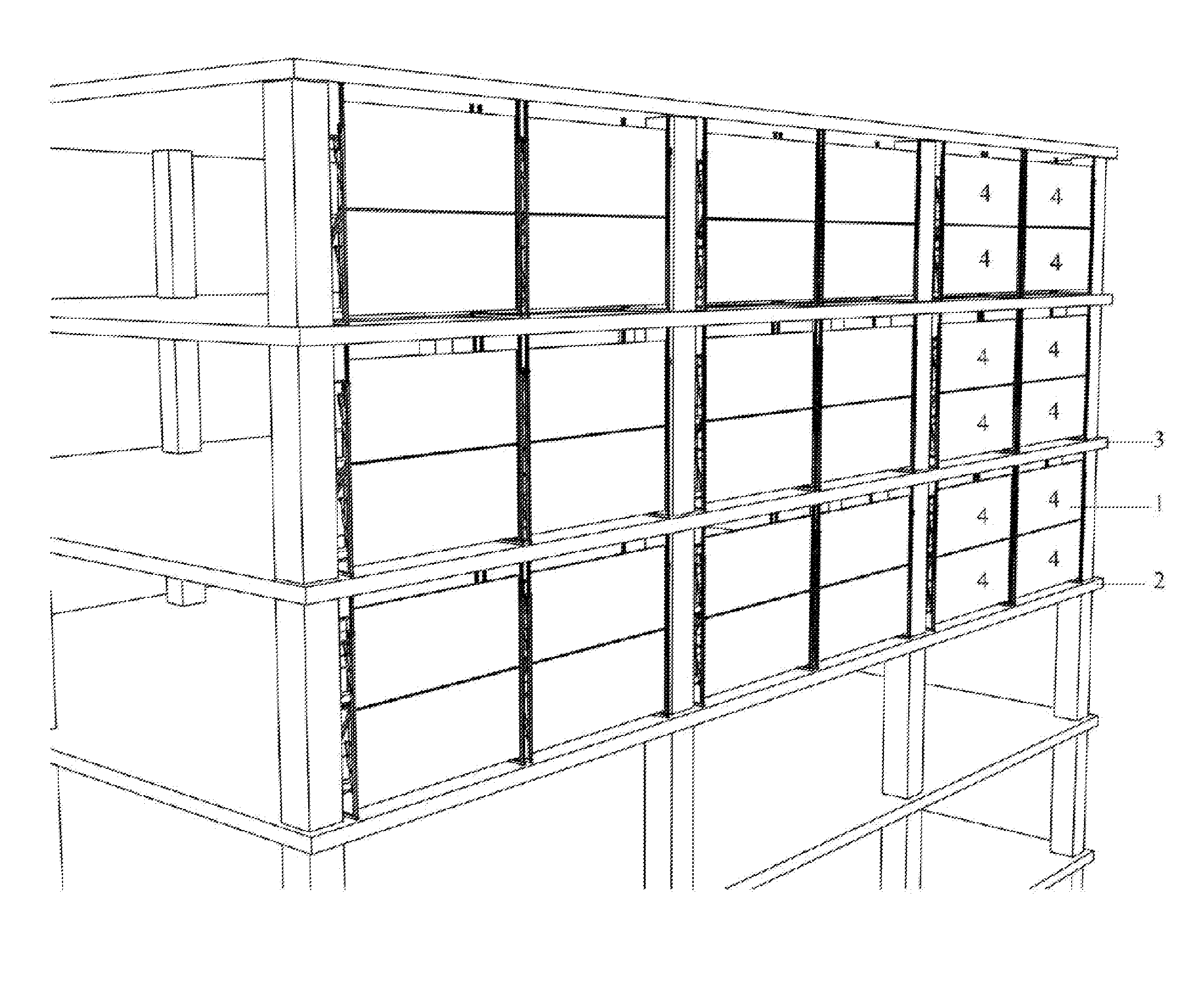
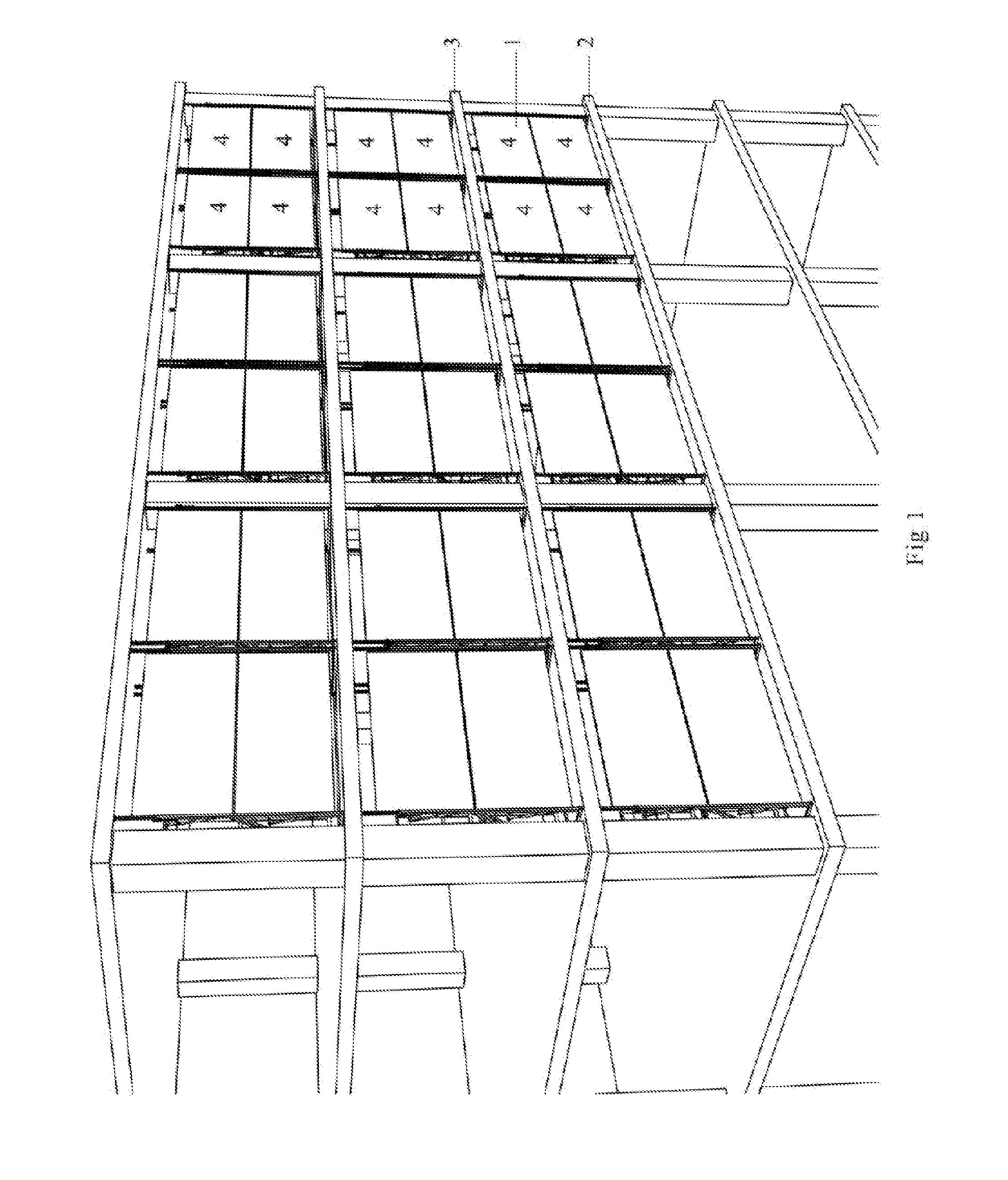
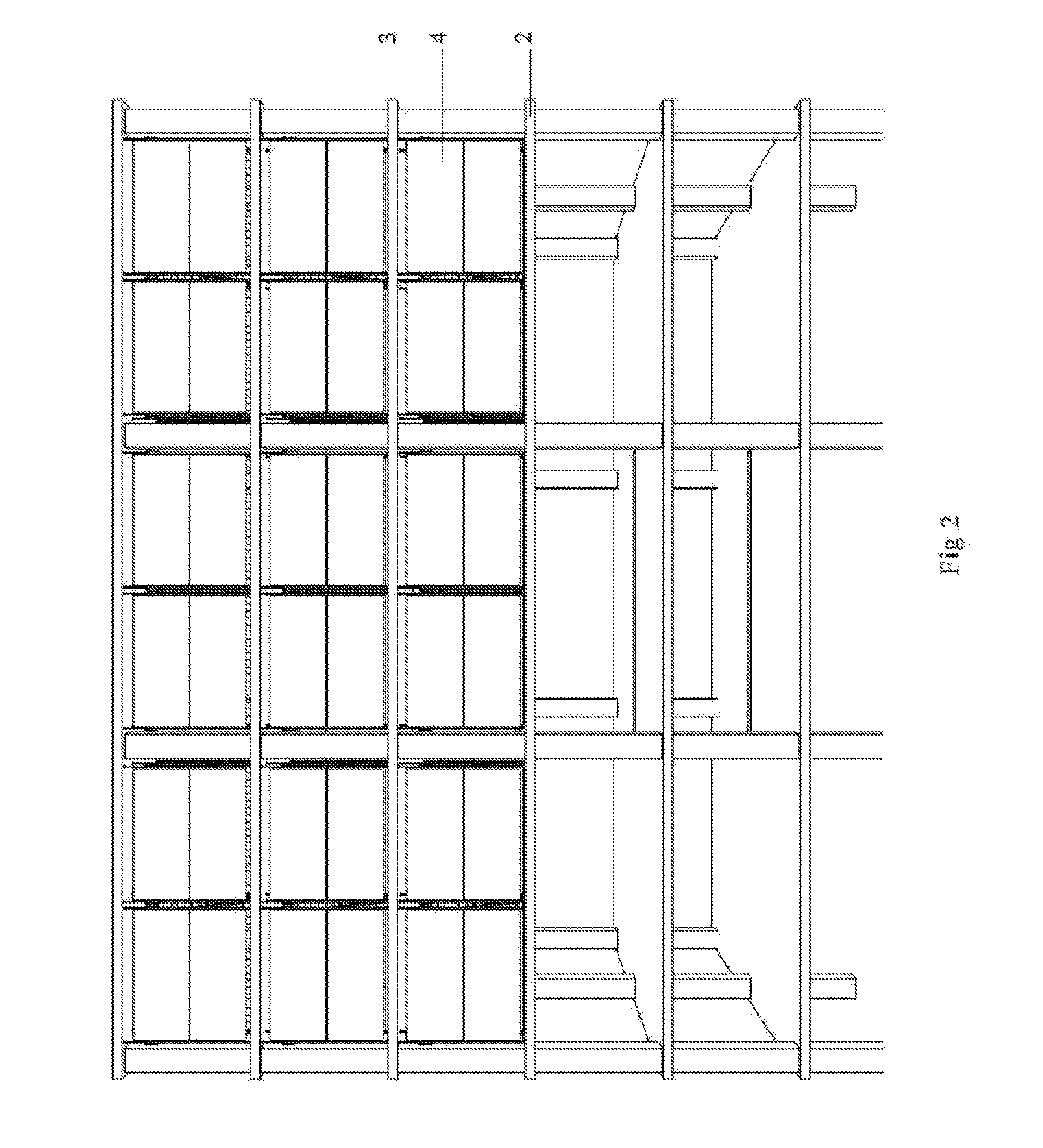
[0032]The present invention may be embodied in a number of different forms. The specification and drawings that follow describe and disclose some of the specific forms of the invention.

[0033]FIG. 1 shows a side perspective view of a multi-story building under construction having a louver display panel system 1 constructed in accordance with one of the embodiments of the invention. The louver display system is shown as it would typically be mounted between the floor structure 2 and the ceiling structure 3 of individual floors of the building, and before the exterior cladding or glass has been installed. Louver display panel system 1 includes one or more display panels 4 for receiving advertising or other printed or graphic material thereon. In the embodiment of the invention shown in FIG. 1 each individual display panel system includes two such display panels that are generally rectangular in configuration with their longitudinal axes situated horizontally, one panel above the other....


PUM


Abstract

A louver display panel system with a display panel for receiving printed or graphic material thereon, a support member to secure the display panel to a building or structure, and a louver movement control means. The display panel is rotationally secured to the support member and forms a louver structure. The louver movement control means maintains the display panel in a first position in a plane generally parallel to the exterior face of the building or structure until a wind load applied to the display panel exceeds a pre-determined value, after which the louver movement control means permits the display panel to rotate toward a second position generally parallel to the direction of the wind to reduce the wind load borne by the display panel. The louver movement control means returns the display panel to its first position when the wind load drops below said pre-determined value.

Description

STATEMENT OF RELATED APPLICATIONS[0001]This application claims the benefit of U.S. Provisional Patent Application No. 61 / 639,311 having a filing date of 27 Apr. 2012.BACKGROUND OF THE INVENTION[0002]1. Technical Field[0003]This invention relates to display panels as could typically be used on a multi-story building, and in particular a louver style display panel system.[0004]2. Prior Art[0005]The construction of multi-story residential or commercial buildings presents a developer with a unique ability to sell advertising space or to display the developer's name during the construction phase. The construction of a multi-story building often attracts the attention of the public making it an ideal display or advertising medium. The difficulty that construction companies and developers have traditionally faced is how to easily and economically display advertising from the building without interfering in its construction, and at the same time without presenting a structure that can be ea...

Claims


Application Information

Patent Timeline
Patent Type & Authority Applications(United States)
IPC IPC(8): G09F15/00
CPCG09F15/0087G09F15/0018G09F19/226
Inventor MELIC, JOHN J.
Owner MELIC JOHN J
Why Eureka
Try Eureka