
Retractable gate

a technology of retractable gates and arm arms, which is applied in the direction of traffic gates, ways, transportation and packaging, etc., can solve the problems of large vertical space above the gate, difficulty in upward motion, and large weight of the long arm of the gate, so as to reduce the requirement of space, reduce wind load, and improve the applicability of the retractable gate

Inactive Publication Date: 2008-06-10
SAFE CROSSINGS
View PDF8 Cites 20 Cited by
  • Summary
  • Abstract
  • Description
  • Claims
  • Application Information

AI Technical Summary

Benefits of technology

[0004]The retractable gate according to the present invention may be raised and lowered (or rotated) between block and park positions. While gravity provides motive forces for retraction (or extension as the gate is raised into the park position, alternate embodiments include further extension and retraction devices to broaden the applicability of the retractable gate according to the present invention.
[0005]Thus, the retractable gate provides reduced wind loading, less space requirement when in the park position, a reduced inertia moment arm by retractable arm sections which are deployed or retracted without requiring additional time to deploy the arm sections in the blocking position.

Problems solved by technology

However, a long gate arm represents a considerable weight and movement inertia, which is further increased by added counter balances.
Moreover, the moved gate requires a place to park when not positioned to block access.
For vertically moving gates which are parked in an upright (or nearly upright) position, the upward motion is difficult especially in the initial stage of being raised from the horizontal, and significant vertical space above the gate is required.
Especially significant for the all gates, long or short, which are parked in the raised position is their vulnerability to wind and other weather related damage.

Method used


Image

  • Retractable gate
  • Retractable gate
  • Retractable gate

Examples


Embodiment Construction

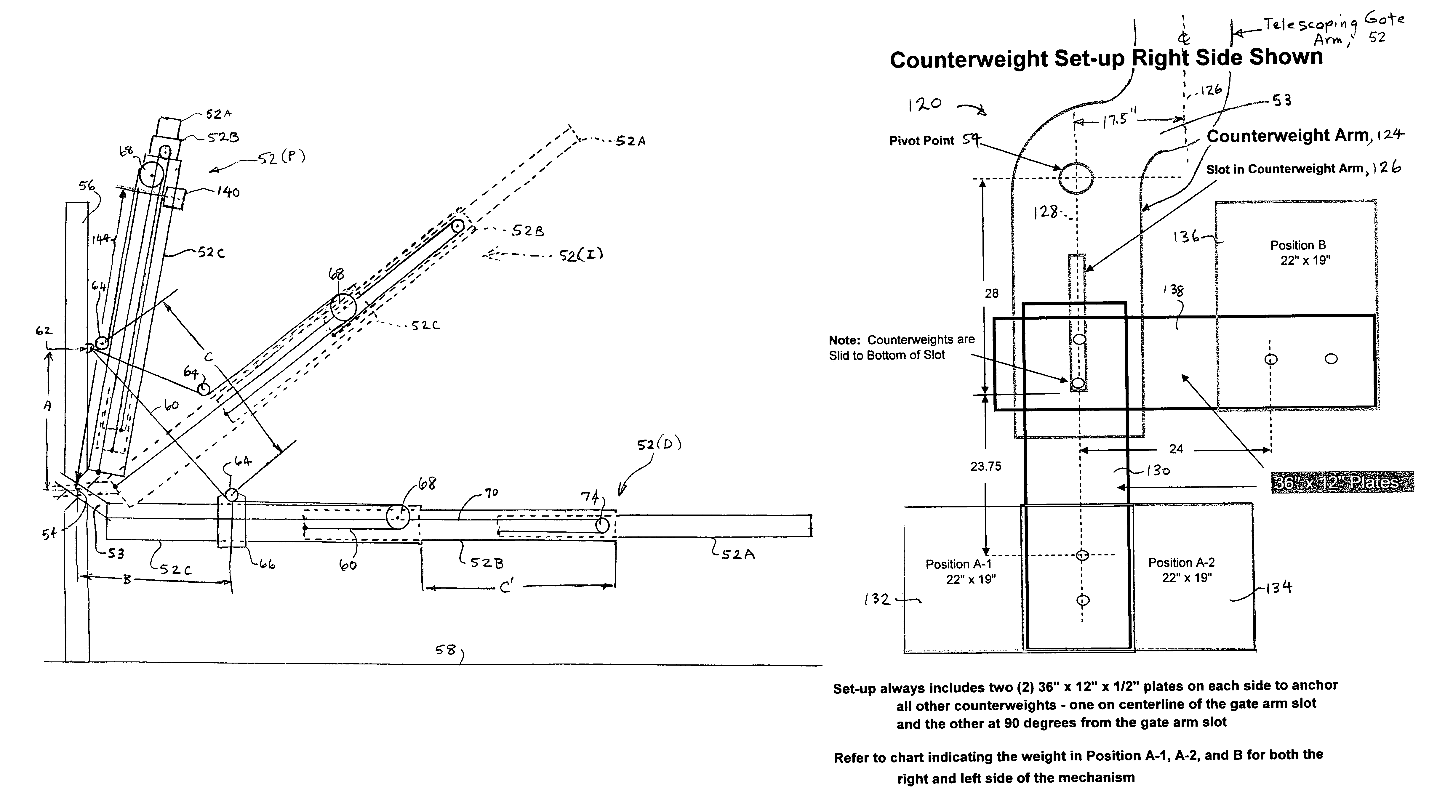
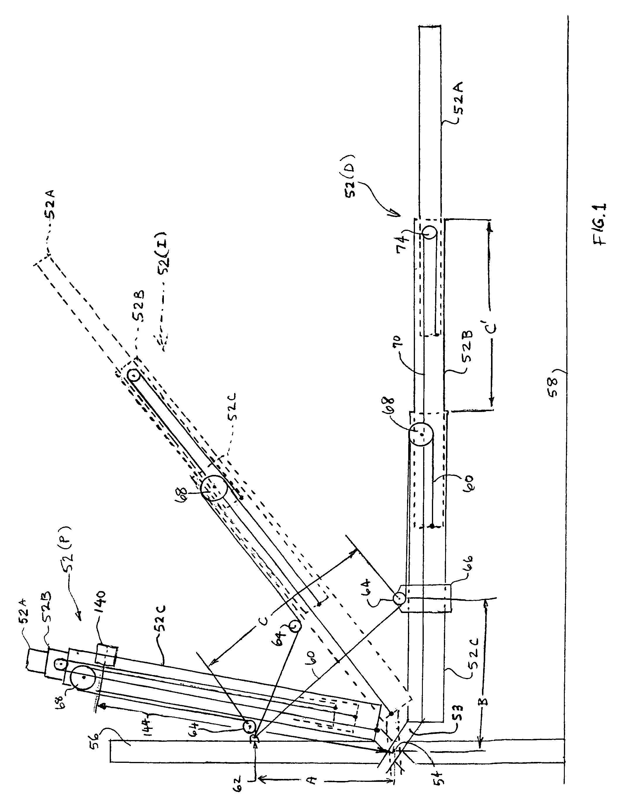
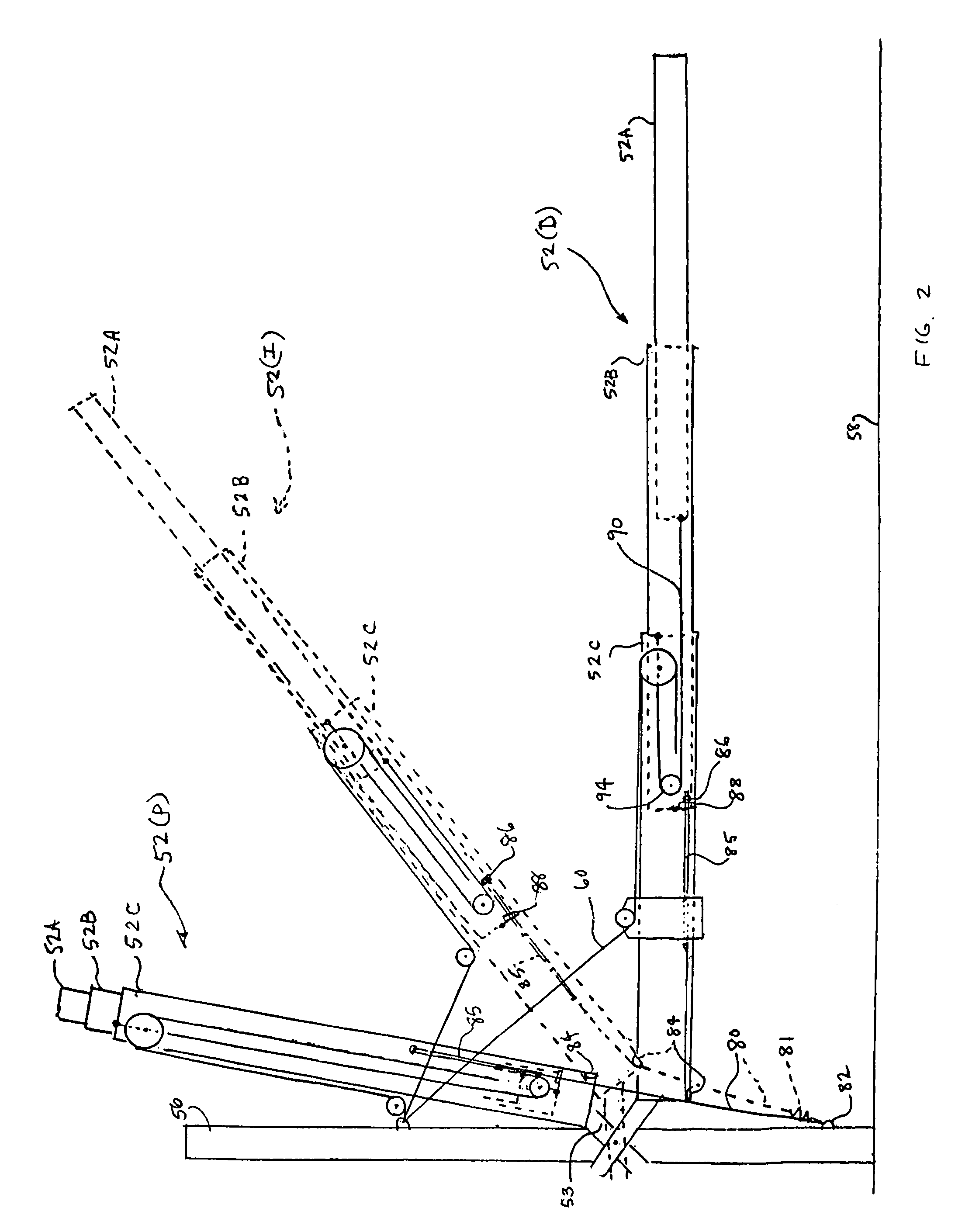
[0018]The exemplary embodiment of FIGS. 1, 2 and 3 showing the gate arm 52 in lowered (blocking) 52(D), intermediate 52(I), and raised up (parked) 52(P) positions. In the exemplary embodiment of FIGS. 1, 2 and 3, the retractable gate arm comprises three tubular segments, 52A, 52B and 52C in which section 52A retracts into section 52B, which retracts into section 52C. Alternate embodiments also include, without limitation, U-shaped, beam, rectangular planar, etc arm section cross-sections, straight or curved along the length of the sections, which may retract adjacent to, over, or any other configuration provided by one skilled in the art. The gate arm 52 includes an end portion 53 which allows the arm 52 to pivot about a pivot 54 and offsets the axis (extending through the center of the arm sections 52A, 52B and 53C) centerline from the pivot 54 so as not to extend therethrough. Moreover, although the embodiment shows the gate arm 52(P) raised substantially perpendicular to the grou...


PUM


Abstract

A retractable gate comprising a movable arm gate having multiple sections which nest or telescope into each other when parked (e.g. upright), and extends into a full length blocking position as it is deployed. The gate arm sections are deployed by the movement of one of the arms, e.g. the outer one section, relative to the ground or a stationary support member and is joined to the stationary support member by a pivot point or bearing, and is connected to the stationary support or ground by a cable connection (or equivalent) which powers the arm sections into extended or retracted positions by movement of the gate about the pivot bearing. A novel corresponding counterweight system provides selectable balance and torque requirements.

Description

FIELD OF THE INVENTION[0001]The present invention relates to movable arm gates, in particular to movable arm gates wherein the arm is retracted in length powered by, and in response to the gate movement.BACKGROUND OF THE INVENTION[0002]Movable arm gates, especially road gates for railroad crossing protection, are often required to extend over a significant expanse of horizontal surface, and to remove that gate completely to permit free travel over that surface within specified time limits. However, a long gate arm represents a considerable weight and movement inertia, which is further increased by added counter balances. Moreover, the moved gate requires a place to park when not positioned to block access. For vertically moving gates which are parked in an upright (or nearly upright) position, the upward motion is difficult especially in the initial stage of being raised from the horizontal, and significant vertical space above the gate is required. The weight and inertia and vertic...

Claims


Application Information

Patent Timeline
Patent Type & Authority Patents(United States)
IPC IPC(8): B61L1/02B61L23/00
CPCB61L29/04
Inventor BURKE, THOMAS J.DINUNZI, JOHN
Owner SAFE CROSSINGS
Learn More