Rotatable building structure

a technology of building structure and rotating structure, applied in the direction of machine/engine, electric generator control, renewable energy generation, etc., can solve the problems of reducing load stability, not intended primarily, and most buildings only have a limited number of apartments

Active Publication Date: 2009-08-20
D INTPROP LTD
View PDF23 Cites 19 Cited by
  • Summary
  • Abstract
  • Description
  • Claims
  • Application Information

AI Technical Summary

Benefits of technology

[0023]In this connection, is an object of the invention to provide a plant of lighting movable elements giving the optical effect of a building which is movable together with the lighting elements.

Problems solved by technology

However, most buildings have only a limited number of apartments with highly desirable exposures.
A limitation of these structures is that they are not intended primarily for use as multi-story apartment buildings or hotels or for providing selective 360° viewing capability.
Another shortcoming is that lack of floor independence decreases load stability.

Method used


Image

  • Rotatable building structure
  • Rotatable building structure
  • Rotatable building structure

Examples


Embodiment Construction

[0055]With specific reference now to the figures in detail, it is stressed that the particulars shown are by way of example and for the purposes of illustrative discussion of the preferred embodiments of the present invention only and are presented in the cause of providing what is believed to be the most useful and readily understood description of the principles and conceptual aspects of the invention. In this regard, no attempt has been made to show aspects of the invention in more detail than is necessary for a fundamental understanding of the invention, the description taken together with the drawings should make it apparent to those skilled in the art how the several forms of the invention may be embodied in practice.

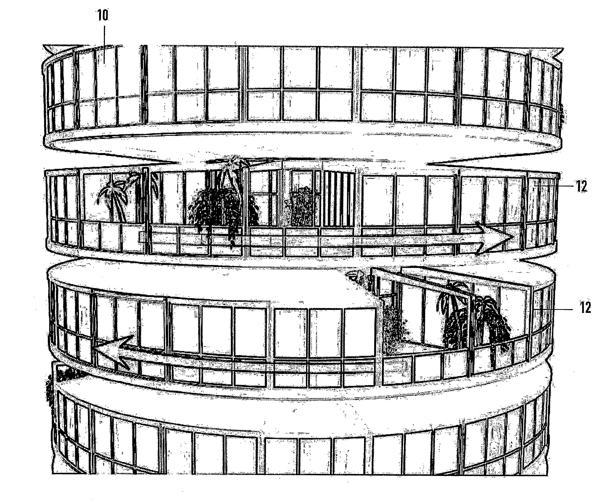
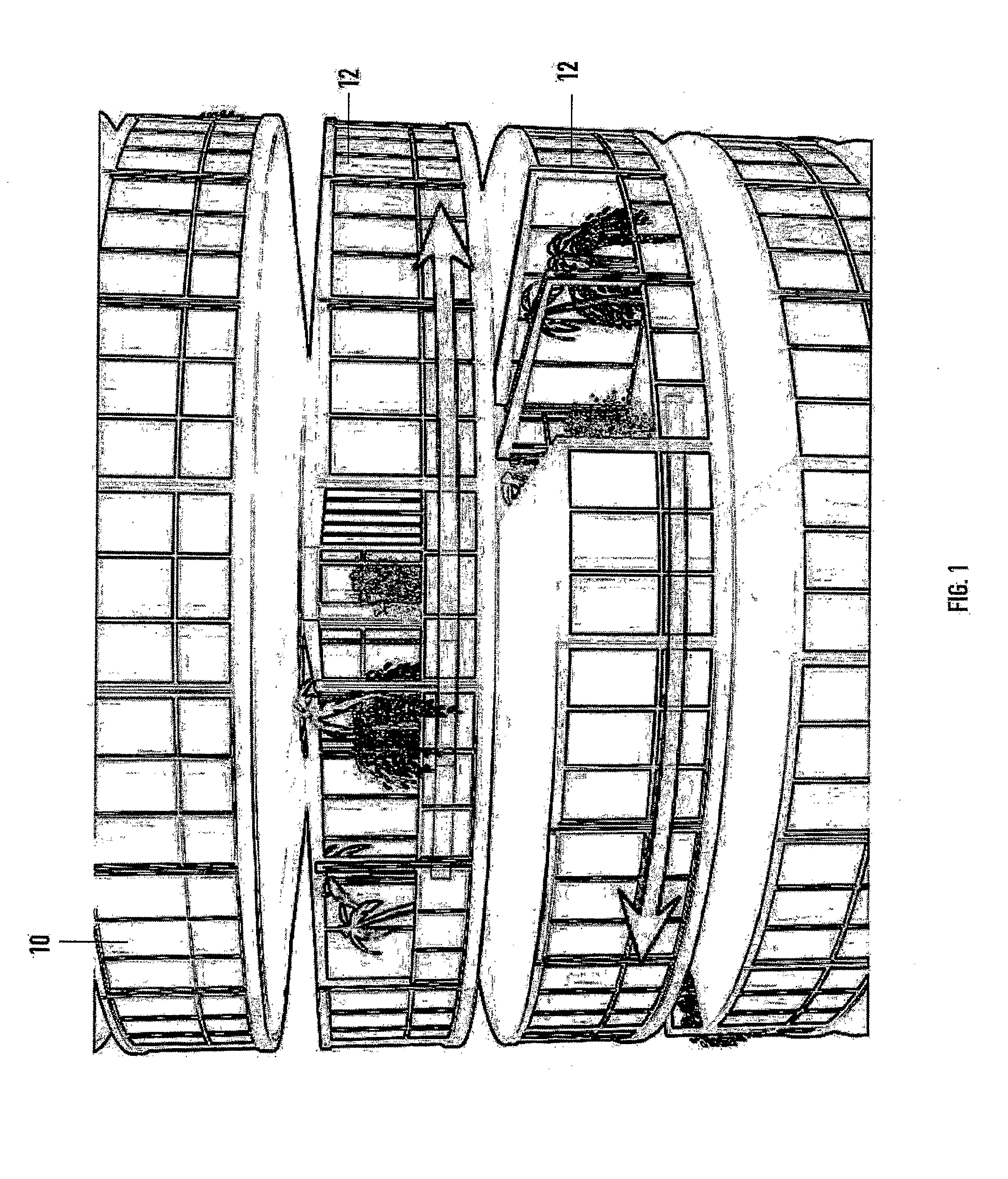
[0056]Referring now in detail to FIG. 1 of the drawings, there is shown a portion of a multi-level rotatable building structure 10 having an independently rotatable suspended floor unit 12. It should be understood that the structure of this invention encompasses a...


PUM


Abstract

A rotatable building structure (10) contains a vertical central core (14) for supporting suspended floor units (12) surrounding the core. An annular platform (22) extends from the core at corresponding floor units for providing accessibility to and from the central core. The floor units contain a drive mechanism (38, 40, 42) for rotational displacement. The wind load on the exterior side of each floor, and/or horizontal wind turbines that turn around the core but is a separate part of the floor itself, solar panels situated as a roof cover on top of each floor and a wind tool (46) deployable from the floor unit provides alternative wind power assist for rotating the floor units.

Description

FIELD OF THE INVENTION[0001]This invention relates to static structures and especially to a structure mounted for in situ repositioning.[0002]In particular, the structure of this invention concerns a building having floor units that are rotatable about a vertical axis.BACKGROUND INFORMATION[0003]The ability of an apartment to command a desirable view is a recognizable factor in determining the salability and economic value of the apartment. However, most buildings have only a limited number of apartments with highly desirable exposures. A solution to this problem is to provide a changeable environment by in situ repositioning of the building. Typically, repositionable building structures were designed with an outer casing rotatably mounted on a spindle; the structures were used principally for observation towers, amusement devices, and / or restaurants for providing patrons with changeable views and not for apartment, hotel and similar dwellings; examples of such structures are shown ...

Claims


Application Information

Patent Timeline
Patent Type & Authority Applications(United States)
IPC IPC(8): E04B1/346E04H9/02E04F11/00E04H9/00E04D13/18E04C2/52E04F19/02E04H1/06B66B9/00F03D9/00
CPCB66B9/187E04B1/3465E04H1/04E04H1/06F03D9/00F03D9/002Y02E10/728F05B2240/91F05B2240/911F05B2240/9112Y02B10/30Y02E10/725F03D11/04F03D13/20F03D9/25Y02E10/74F03D3/0472F03D9/34Y02E10/72
Inventor FISHER, DAVIDFISHER, LAURA MICOL
Owner D INTPROP LTD
Why Eureka
Try Eureka