
Reduced four-wave mixing optical fiber for wavelength-division multiplexing

a four-wave mixing, wavelength-division multiplexing technology, applied in the field of optical fibers, can solve the problems of easy removal, increase in error, and four-wave mixing (fwm)

Inactive Publication Date: 2005-02-01
TERRACOMM RES
View PDF9 Cites 0 Cited by
  • Summary
  • Abstract
  • Description
  • Claims
  • Application Information

AI Technical Summary

Benefits of technology

In another aspect of the invention, the core of the optical fiber includes a range of group index values uniformly distributed throughout the core, each wavelength in the specified range of wavelengths being associated with a particular group index value in the range of group index values and the light potentially producing a nonlinear optical effect. The optical fiber also includes an amount of at least one dopant uniformly dispersed throughout the core such that no two distinct wavelengths in the specified range of wavelengths are associated with the same, particular group index value in the range of group index values, thereby causing the nonlinear optical effect to be suppressed.

Problems solved by technology

The demand for higher optical power throughput and wider range of transmitted wavelengths has led to an increase in the occurrence of error due to nonlinear optical effects produced during light propagation through the optical fiber.
Four-wave mixing (FWM) is especially problematic in WDM networks because this nonlinear optical effect leads communication errors that cannot be easily removed by known solutions such as, for example, wavelength filtering equalization.
FWM is especially problematic in optical communications if the new wavelengths produced by the FWM process overlap the assigned wavelengths of existing WDM channels because it is difficult to distinguish between the legitimate optical data signals at these existing WDM channels and the error signal superimposed thereon as the result of FWM.
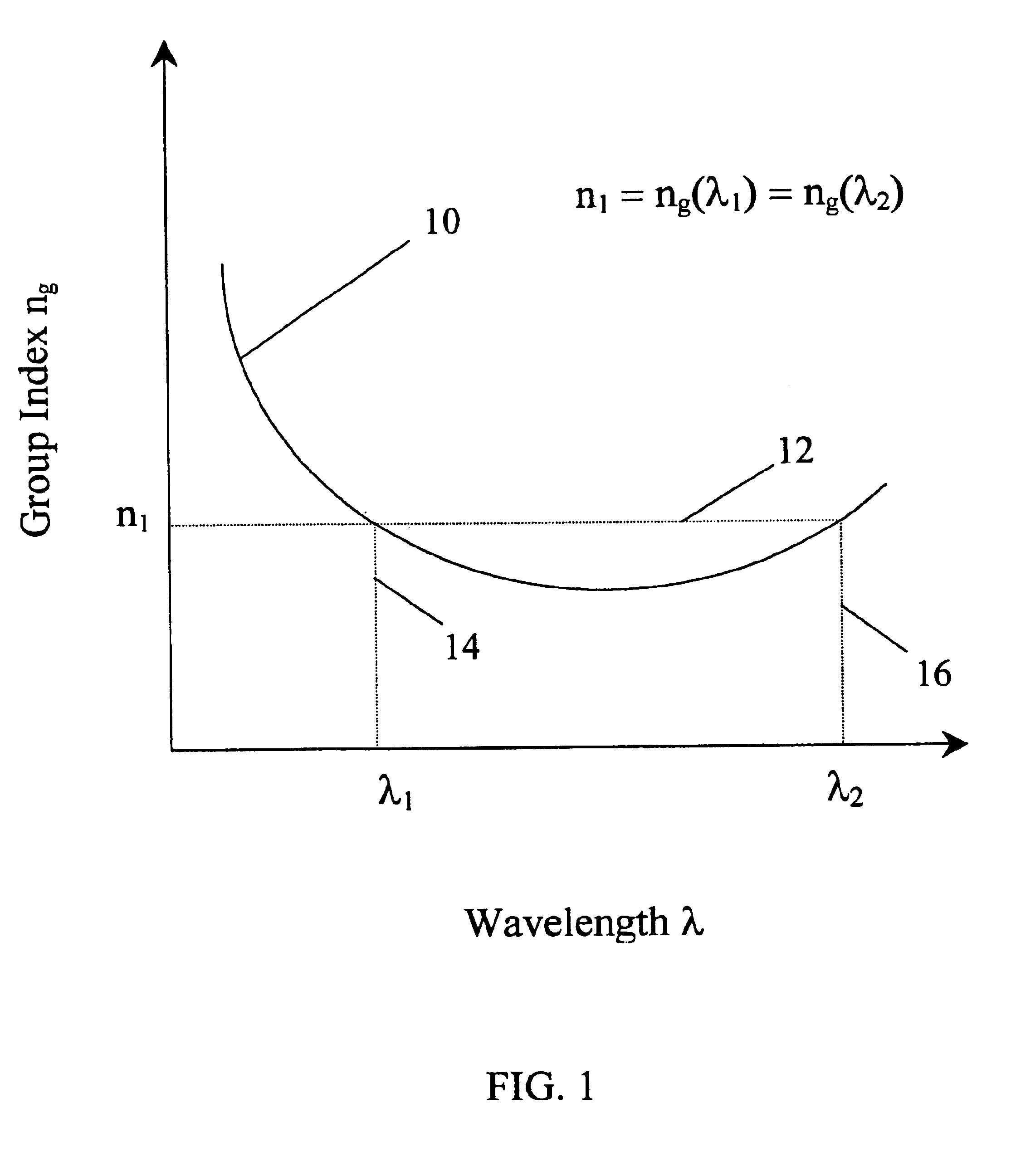
In other words, the longer the potentially combining wavelengths travel together down the optical fiber at the same group velocity, the higher the risk of communication error resulting from FWM.
As a result, the FWM efficiency for the combination of the shorter wavelengths and the longer wavelengths in the optical fiber communication wavelength range is high, therefore leading to a high probability of potential error introduced in the transmitted optical signals.
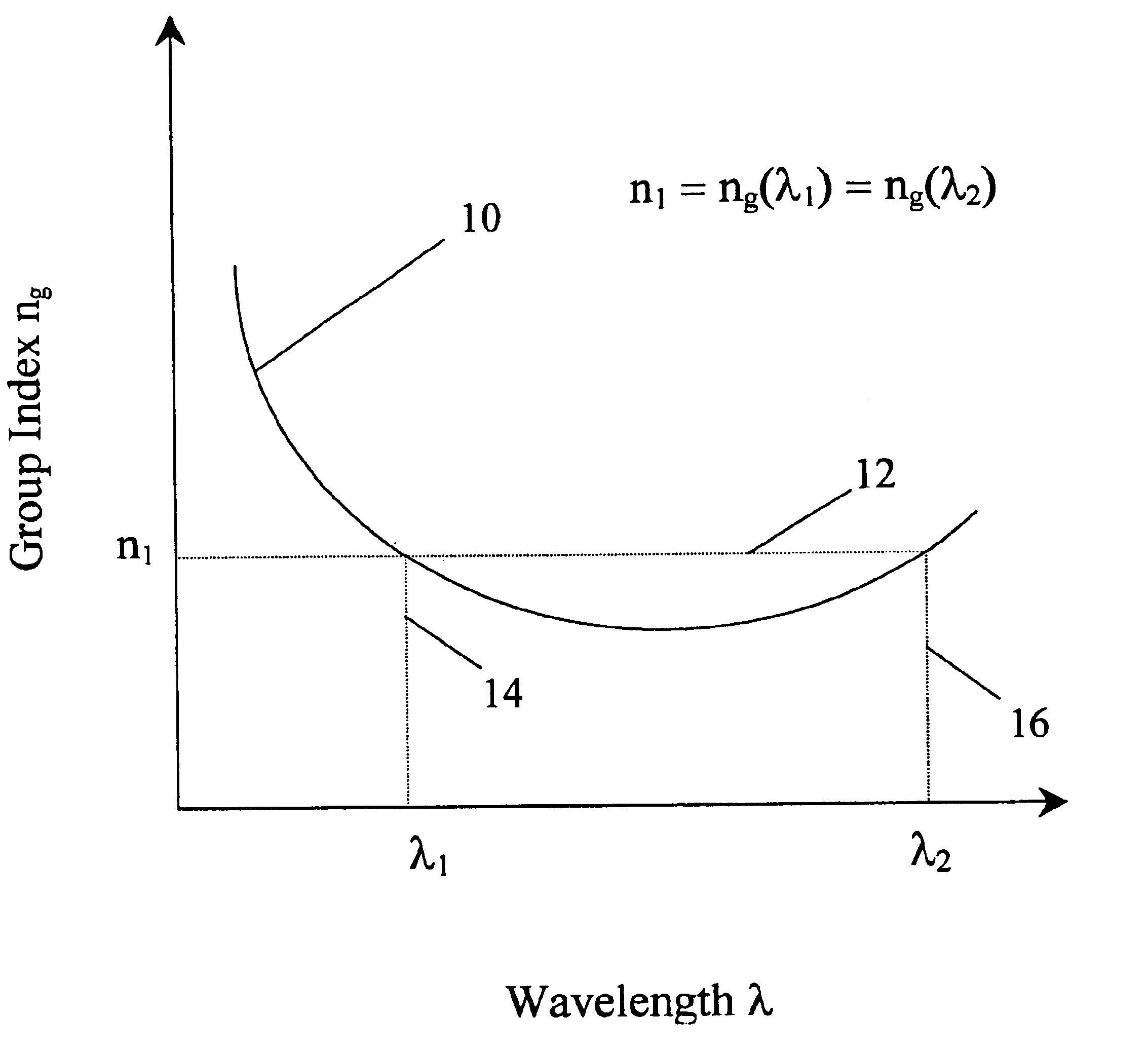
In the example shown in FIG. 1, the FWM efficiency for the combination of λ1 with λ2 is high, therefore leading to a high probability of potential error occurring due to FWM.
Advances in chromatic dispersion shifting and reduction in optical fibers have actually exacerbated the problem because FWM efficiency increases around the wavelength at which chromatic dispersion is zero.
Furthermore, increased variety of wavelengths used at the WDM channels also exacerbate the FWM problem because more optical wavelength combinations are available for the FWM process.
However, reduction of optical power leads to problems such as the cost associated with the need for additional repeaters to regenerate the optical signals and the potential increase in bit error rates due to signal weakness.
The technological demand for increased distance between repeaters, reduced cost and more reliable data transmission makes this approach impractical.
In addition, the LEAF has the characteristics of NZ-DSF such that FWM efficiency is further reduced.
A problem common to the aforedescribed prior art approaches is the manufacturing complexity of the specialty optical fibers.
The design and fabrication of these speciality fibers can be complicated and costly.

Method used


Image

  • Reduced four-wave mixing optical fiber for wavelength-division multiplexing
  • Reduced four-wave mixing optical fiber for wavelength-division multiplexing
  • Reduced four-wave mixing optical fiber for wavelength-division multiplexing

Examples


Embodiment Construction

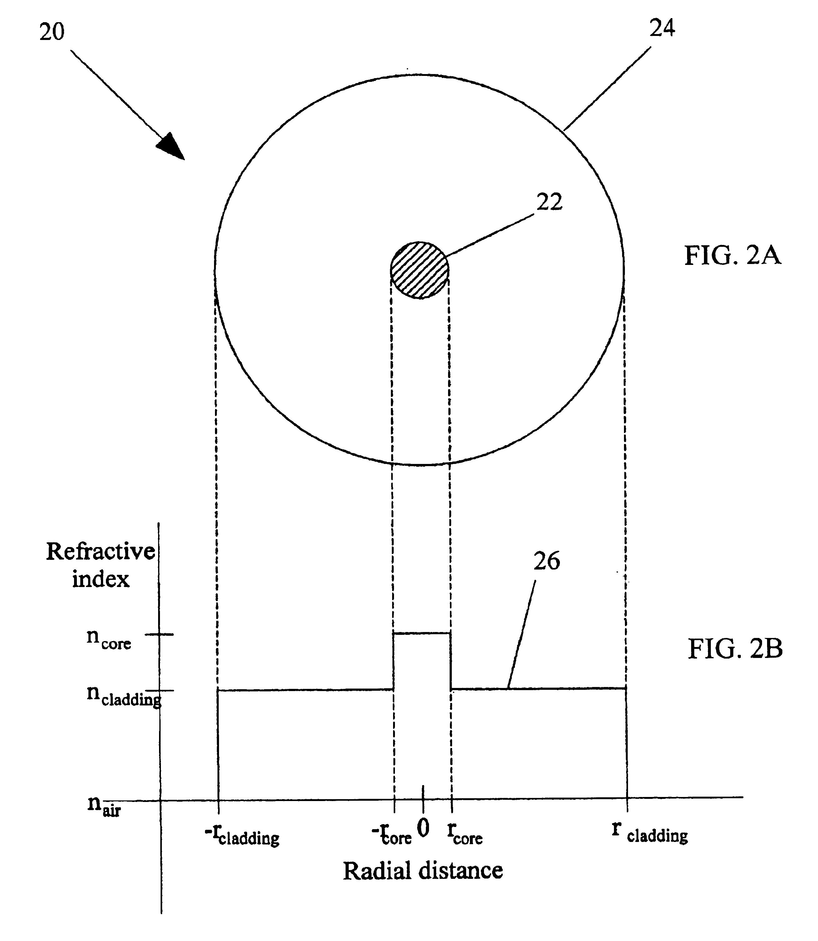
Turning again to the drawings, attention is immediately directed to FIG. 2A, which illustrates one embodiment of an optical fiber, generally indicated by the reference numeral 20. Optical fiber 20 includes a core 22 surrounded by a cladding 24. The dimensions of core 22 and cladding 24 are similar to those of a conventional single mode fiber, which commonly has a core diameter of 4 μm and a cladding diameter of 125 μm. Core 22 and cladding 24 are based on silica glass (SiO2) or a similar material. Core 22 and cladding 24 are designed to have different values of refractive index such that light of a specified range of wavelengths is guided through the optical fiber.

The relative values of the refractive index of air, cladding and core are shown in FIG. 2B by line 26. As in the case of conventional single mode fiber, the refractive index value of the cladding (ncladding) is relatively higher than that of air (nair), and the core is composed of a material with a refractive index value (...


PUM


Abstract

An optical fiber includes a core for guiding light of a specified range of wavelengths therethrough, each wavelength in the specified range of wavelengths traveling through the core at a particular group velocity and the light potentially producing a nonlinear optical effect. The optical fiber also includes a cladding formed around the core for substantially containing the light within the core. The optical fiber further includes a predetermined amount of at least one dopant uniformly dispersed throughout the core such that no two distinct wavelengths in the specified range of wavelengths travel through the core at the same, particular group velocity, thereby causing the nonlinear optical effect to be suppressed.

Description

BACKGROUND OF THE INVENTIONThe present invention relates generally to optical fibers and, more particularly, to optical fibers in which the occurrence of four-wave mixing is reduced.The advent of wavelength-division multiplexing (WDM) in optical networking has increased the demands placed on optical fibers. Manufacturers are pressured to produce optical fibers that are capable of carrying optical signals on a wider range of wavelengths and over longer distances with less loss than can be accomplished with presently available optical fibers. Concurrent developments in optical sources for WDM have increased the amount of optical power and bit rates that must be transmitted through the optical fiber.The demand for higher optical power throughput and wider range of transmitted wavelengths has led to an increase in the occurrence of error due to nonlinear optical effects produced during light propagation through the optical fiber. Four-wave mixing (FWM) is especially problematic in WDM n...

Claims


Application Information

Patent Timeline
Patent Type & Authority Patents(United States)
IPC IPC(8): G02B6/02
CPCG02B6/02G02B6/02214
Inventor PUZEY, KENNETH A.
Owner TERRACOMM RES
Learn More