Optical effect pigment

a technology of effect pigments and optical effects, applied in the field of effect pigments, can solve the problems of weakened effect pigment security potential, and the position that prior art magnetic effect pigments on printed substrates cannot be controlled by magnetic fields, and achieve the effect of substantial production cost savings

Pending Publication Date: 2020-11-12
ANDRÉS RUIZ QUEVEDO
View PDF0 Cites 0 Cited by
  • Summary
  • Abstract
  • Description
  • Claims
  • Application Information

AI Technical Summary

Benefits of technology

[0026]In a variant of the first embodiment and as an additional security measure for a printed document, the effect pigment comprises a luminescent material which, when excited by an energy source, emits a response in the form of an electromagnetic wave. The luminescent material can be added preferably to the dielectric layers (35a, 35b) or it can be incorporated in the form of a luminescent layer added as a respective additional layer to each of the stacks of layers (31, 32). In either case, the luminescent material has different features on each layer, in order to obtain a different luminescent response on each side of the pigment, this being another example of a double response obtained with just one pigment.
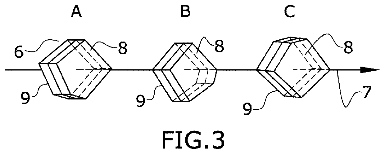
[0027]According to a second preferred embodiment of the invention, the layers in the effect pigment are arranged in one stack of layers comprising an absorber layer, a dielectric layer and a reflector layer and the pigment also comprises a magnetic element consisting of at least one magnetic layer with an out-of-plane magnetisation.
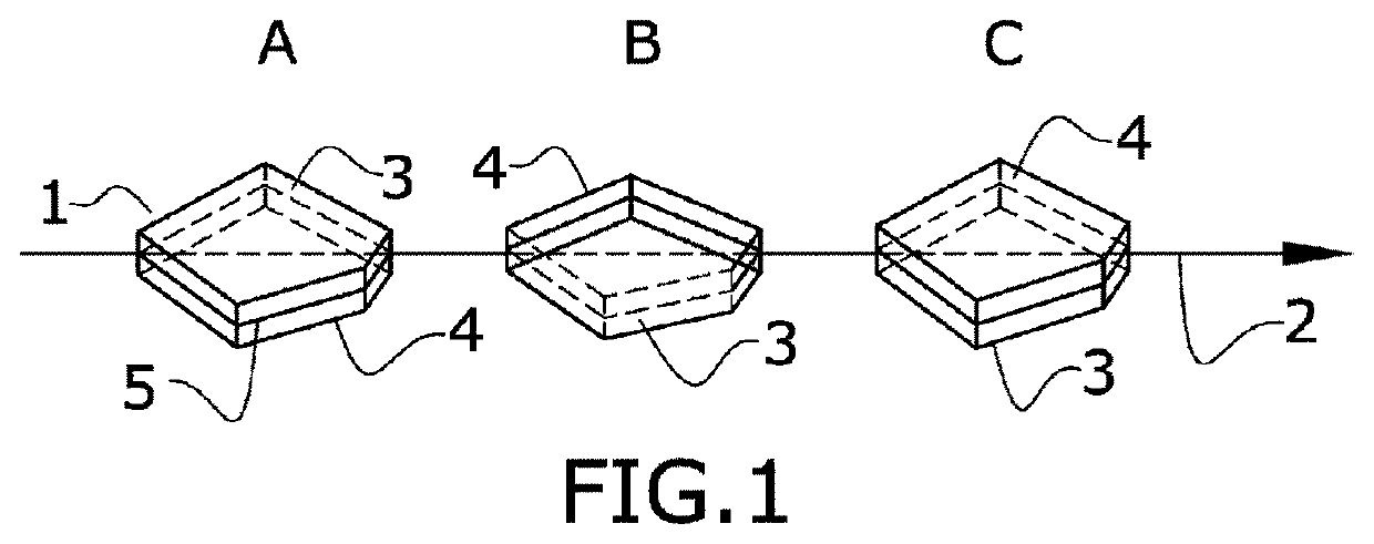
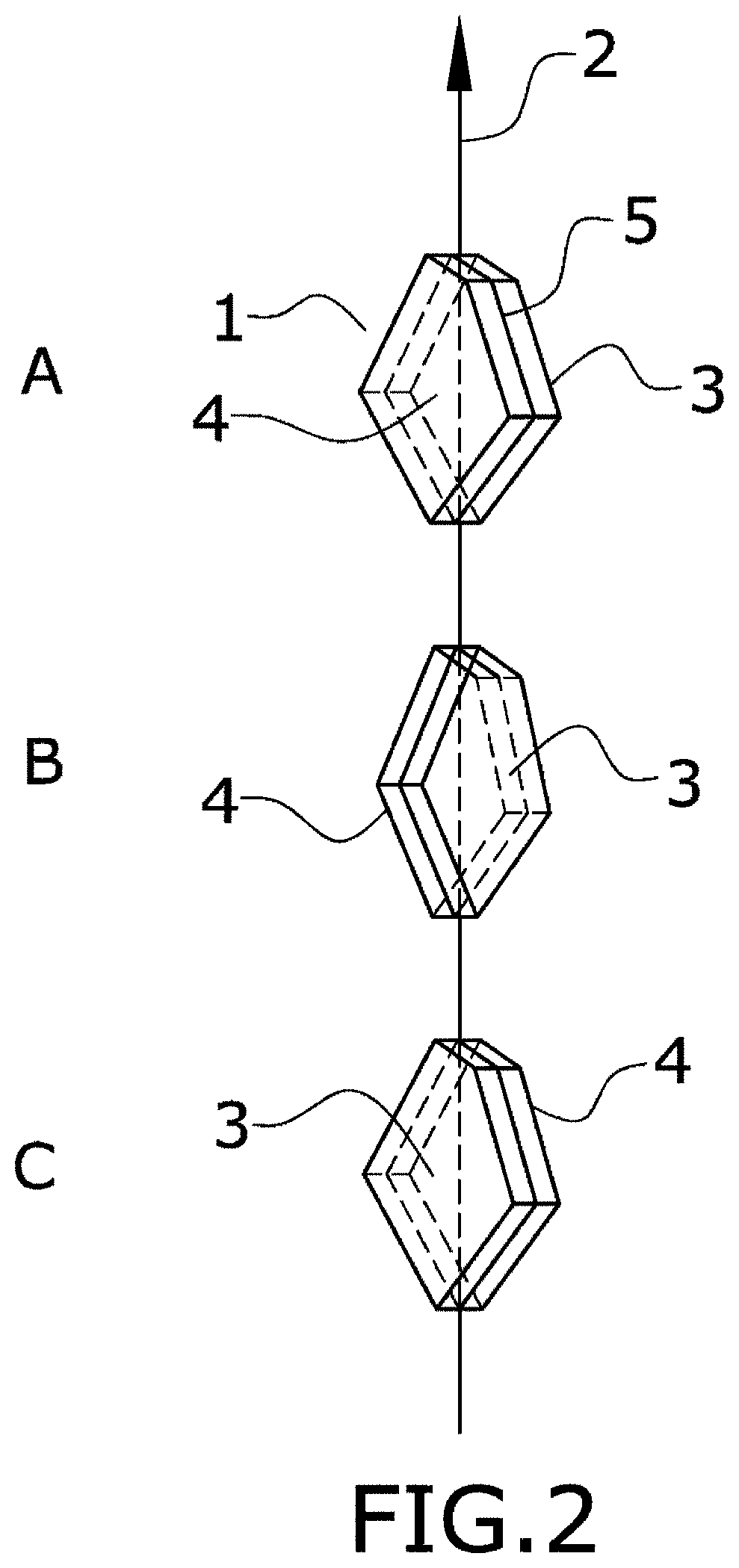
[0028]As already mentioned, known security pigments with a parallel magnetisation with respect to their plane need two symmetrical stacks of layers in order to ensure that the desired single optical effect is produced, whereas according to the first preferred embodiment of this invention, a double-stack magnetic effect pigment can produce two different optical effects. Now this second preferred embodiment has the advantage that a single-stack pigment with out-of-plane magnetisation renders the same single optical effect that a symmetric double-stack pigment with in-plane magnetisation. The reason is evident from the preceding description: the perpendicular magnetisation can be used to ensure that all pigments will lie on the substrate with the magnetic element facing downwards to the substrate and the single stack of layers facing upwards to produce a single optical effect. Therefore, the additional stack of layers becomes unnecessary and can be disposed with, bringing substantial production costs savings.
[0029]According to a third preferred embodiment of the invention, the layers in the effect pigment are arranged in a single stack of layers comprising an absorber layer and a dielectric layer and not comprising a reflector layer. The pigment also comprises a magnetic element consisting of at least one magnetic layer with an out-of-plane magnetisation. Said magnetic element comprises nickel particles and Aluminum. The presence of Aluminum allows the magnetic element to function as well as a reflector layer. Therefore, this embodiment can save yet another layer in the structure of the effect pigment.
[0030]According to a fourth preferred embodiment, the layers in the effect pigment are arranged in two stacks of layers each one comprising an absorber layer and a dielectric layer and not comprising a reflector layer. The pigment also comprises a magnetic element consisting of at least one magnetic layer with an out-of-plane magnetisation. Said magnetic element comprises nickel particles and Aluminum. The presence of Aluminum allows the magnetic element to function as well as a reflector layer for both stacks of layers. Therefore, this embodiment allows a saving of two layers in the structure of a double-stack effect pigment.
[0031]The claimed effect pigments with an out-of-plane magnetisation, as opposed to the effect pigments with an in-plane magnetisation as known in the state of the art, are based on the general principle of Physics that the combination of two uniaxial magnetic anisotropies (of different physical origin) with easy axis in perpendicular directions produces a single uniaxial anisotropy whose easy axis lies in the direction of the stronger one, and whose magnitude is the difference between them, this effect being particularly relevant where the magnetic element is a thin layer. The claimed pigments are made with magnetic layers with an anisotropy constant Ku, which are given an appropriate geometry to create a shape anisotropy Ks in a direction perpendicular to Ku and weaker than it. The resulting anisotropy has an effective anisotropy Kef=Ku−Ks. This phenomena is explained in, among others, GRAHAM, et al. Introduction to magnetic materials. New Jersey: Wiley, 2009. p. 234-238.

Problems solved by technology

The optical variability of these pigments is due to an interference effect, whereby the light falling upon a pigment is partially reflected and partially transmitted or diffracted.
Although of a lesser quality in terms of brightness and colour shifting, the cheap availability of these coatings has weakened the security potential of effect pigments, since a document may be reproduced by a high-quality colour printer or scanner and its optically variable portion can be added using a commercially available effect pigment.
However, another aspect of the position that a prior art magnetic effect pigment will have on the printed substrate cannot be controlled by way of magnetic fields, namely, which face of the pigment will fall “face down” on the substrate and which one “face up”.

Method used


Image

  • Optical effect pigment
  • Optical effect pigment
  • Optical effect pigment

Examples


first embodiment

[0051]In a variant of the first embodiment, the effect pigment comprises a luminescent material which is added to the at least two dielectric layers (35a, 35b). Suitable luminescent materials are disclosed in WO 02 / 040599 A (FLEX PRODUCTS INC.) 23 May 2002. Addition of the luminescent material is made by the same deposition process that will be described hereinafter, by including the luminescent material together with the dielectric material in the target employed for the deposition. In a further variant, the luminescent material can be incorporated in the form of a luminescent layer added to each of the stacks of layers (31,32). Suitable materials for these layers are the same described in above-mentioned WO 02040599 A. The luminescent material is added according to the same process applicable to the other layers which will be referred hereinafter. The luminescent response may or may not be in the visible spectrum. In the latter case, the response must be detected using an appropri...

third embodiment

[0059]Magnetic layers (45) with reflector properties as incorporated to the third embodiment are obtained by sol-gel techniques described as follows in KRAUS, et al. Synthesis and magnetic properties of Ni—Al2o3 thin films. J. appl. phys. 1997, no. 82, p. 1189-1195. sol-gel layers are deposited from NiAl2O4 spinel precursors derived by mixing stoichiometric quantities of solutions prepared from nickel 2-ethylhexanoate and aluminum tri-sec-butoxide in 2-methoxyethanol. The nickel solution is prepared by mixing nickel 2-ethylhexanoate with 2-methoxyethanol in a molar ratio of 1:5, refluxing at 140° C. for 12 h, centrifuging, and decanting to produce a 0.6M solution. In a separate flask, aluminum tri-sec-butoxide is dissolved in 2-methoxyethanol in a molar ratio of 1:10 and refluxed for 30 min at 140° C. The volume is reduced by distillation at a temperature of 140° C. and 200 mm Hg. Acetic acid is then added to the aluminum precursor in a molar ratio of 7:1. This solution is stirred a...


PUM

PropertyMeasurementUnit
thicknessaaaaaaaaaa
thicknessaaaaaaaaaa
thicknessaaaaaaaaaa

Abstract

Optical effect pigment comprising a plurality of layers and a magnetic element, the layers can be arranged in two stacks of asymmetric layers or in a single stack of layers and comprise at least an absorber layer and at least a dielectric layer and can further comprise a reflector layer. The magnetic element presents a magnetisation which is out-of-plane, i.e. predominantly perpendicular to the plane of the pigment, which allows a deposition on the printing substrate whereby the face of the pigment lying up or down on the substrate can be predetermined. Such effect pigment has applications in many fields and specifically in security printing, where due to controlled deposition for instance a double-stack pigment will produce a different optical effect on each of its faces.

Description

TECHNICAL FIELD[0001]The invention pertains to the field of effect pigments used for different purposes including security printing, particularly to effect pigments comprising a plurality of layers and a magnetic element.BACKGROUND ART[0002]An effect pigment, also called “Optically Variable Pigment” (OVP) among other names, is a particle presenting the following basic features: a) It has an elongated flake, plate or platelet shape and therefore it has two faces, b) its structure is made up of a number of layers and c) it renders an optical effect which depends mostly on the number, composition, thickness and index of refraction of its layers. Optical effects comprise colour-changing effects, holographic effects and luminescent effects. The name “effect pigment” or simply “pigment” shall be used throughout this patent.[0003]Effect pigments have many industrial applications, especially in the cosmetic, coatings and security printing domains. Pigments can be dispersed in a liquid mediu...

Claims


Application Information

Patent Timeline
Patent Type & Authority Applications(United States)
IPC IPC(8): C09C1/00C09D11/322
CPCC01P2006/42C09D11/322C09C2200/1054C09C1/0015C09C2210/50C01P2006/60C09C2200/24C09D11/107C09D11/324
Inventor RUIZ QUEVEDO, ANDRÉS
Owner ANDRÉS RUIZ QUEVEDO
Why Eureka
Try Eureka