
Fiberoptics, fiberoptic transmission line and optical transmission system

a technology of fiberoptic transmission lines and fiberoptic fibers, applied in the field of optical fiber, optical fiber transmission lines, optical transmission systems, can solve the problems of easy further deterioration of signal light waveform, and achieve the effect of reducing wavelength dependence, reducing wavelength dependence, and effectively non-linear optical effects

Inactive Publication Date: 2006-11-16
SUMITOMO ELECTRIC IND LTD
View PDF1 Cites 0 Cited by
  • Summary
  • Abstract
  • Description
  • Claims
  • Application Information

AI Technical Summary

Benefits of technology

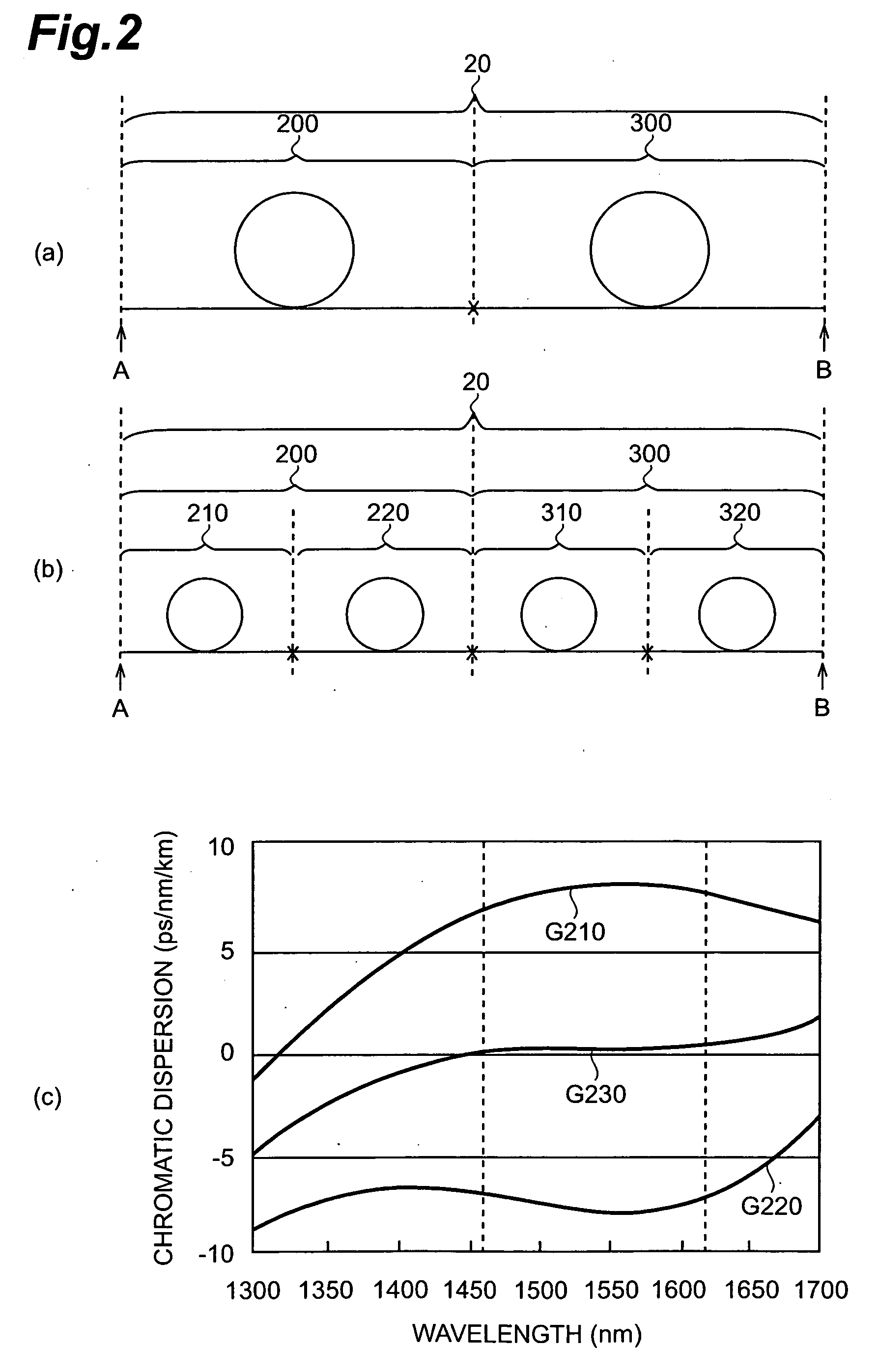
[0020] As described above, in accordance with the present invention, the optical fiber transmission line comprising the first optical fiber having a positive chromatic dispersion such that its wavelength dependence is reduced over a wide wavelength range of 1460 nm to 1620 nm, and the second optical fiber having a negative chromatic dispersion such that its wavelength dependence is reduced over the wavelength range. In this way, each of the first and second optical fibers has a chromatic dispersion of a different polarity, thereby controlling accumulated chromatic dispersion at low level for a whole optical fiber transmission line, while the chromatic dispersion occurs to some extent in each of the first and second optical fibers, thereby controlling effectively non-linear optical effects such as four-wave mixing.

Problems solved by technology

The chromatic dispersion depends greatly on wavelengths, while a waveform of the signal light is deteriorated easily when the chromatic dispersion is large.
In addition, the waveform of the signal light is further deteriorated due to an interaction between the chromatic dispersion and non-linear optical phenomena.

Method used


Image

  • Fiberoptics, fiberoptic transmission line and optical transmission system
  • Fiberoptics, fiberoptic transmission line and optical transmission system
  • Fiberoptics, fiberoptic transmission line and optical transmission system

Examples


Embodiment Construction

[0027] In the following, the best modes for carrying out the inventions will be explained in detail with reference to FIGS. 1-5. In the explanation of the drawings, the same elements will be denoted by the same reference symbols and these redundant descriptions will be omitted.

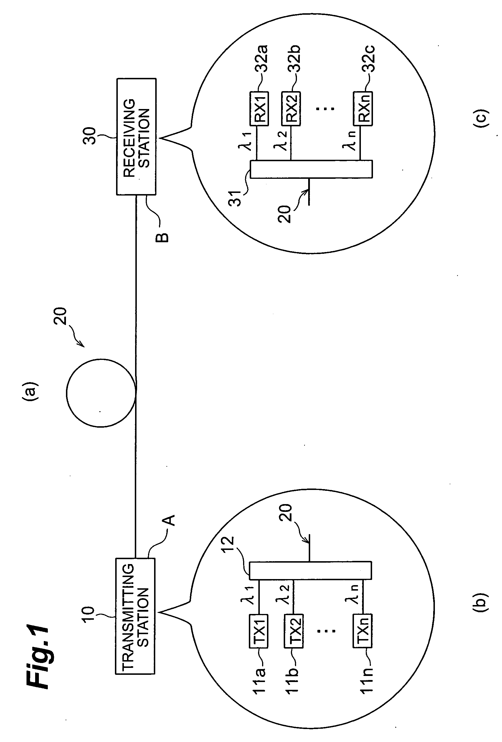
[0028]FIG. 1 is a diagram showing the constructions of an optical transmission system, a transmitting station, and a receiving station according to the present invention. The optical transmission system, shown in the area (a) of FIG. 1, composes a transmitting station 10 for transmitting signal light, an optical fiber transmission line 20 as a transmission medium through which the signal light propagates, and a receiving station 30 for receiving the signal light. A signal input end A of the optical fiber transmission line 20 is connected to a signal output end of the transmitting station 10, while a signal output end B of the optical fiber transmission line 20 is connected to the signal input end of the recei...


PUM


Abstract

The present invention provides an optical transmission system and so on having a structure that enables to reduce variations between wavelengths in chromatic dispersion over a wide wavelength range and control non-linear optical effects. An optical fiber transmission line comprises a first optical fiber having a positive chromatic dispersion such that its wavelength dependence is reduced over a wide wavelength range, and a second optical fiber having a negative chromatic dispersion such that its wavelength dependence is reduced over the wavelength range. In this way, the first and second optical fibers each have a chromatic dispersion of a different polarity, thereby controlling accumulated chromatic dispersions at low level for a whole optical fiber transmission line, while the chromatic dispersion occurs to some extent in each of the first and second optical fibers, thereby controlling effectively non-linear optical effects such as four-wave mixing.

Description

TECHNICAL FIELD [0001] The present invention relates to an optical fiber, an optical fiber transmission line, and an optical transmission system that are available as an optical transmission line suitable for to an optical transmission for wavelength division multiplexing (WDM). BACKGROUND ART [0002] A WDM optical transmission system is the one that transmits signal light involving a plurality of channels having different wavelengths from each other by way of an optical fiber as a transmission line, and that enables an information transmission of high speed and large capacity. Typically, a transmission fiber is an optical fiber mainly composed of silica and having the smallest transmission loss with respect to light in the 1.55 μm wavelength band. In the WDM transmission system having such an optical fiber as an optical transmission line, signal light in the 1.55 μm wavelength band is used. On the other hand, a standard single mode optical fiber having a zero dispersion wavelength i...

Claims


Application Information

Patent Timeline
IPC IPC(8): G02B6/02G02B6/028G02B6/036H04B10/2507H04B10/2525H04B10/2563H04J14/00H04J14/02
CPCG02B6/02009G02B6/02223G02B6/02242H04B10/2563G02B6/02271G02B6/03644G02B6/29377G02B6/02257
Inventor HATAYAMA, HITOSHISASAOKA, EISUKE
Owner SUMITOMO ELECTRIC IND LTD
Learn More