Method of manufacturing surface textured high-efficiency radiating devices and devices obtained therefrom

a technology of radiating devices and surface textured, which is applied in the direction of optics, instruments, optical elements, etc., can solve the problems of reducing the efficiency of the total light emission of the device, the device is not suitable for integration in large arrays, and the device is inherently slow, so as to reduce the recombination effect of charge carriers, improve the efficiency and the speed of the device, and reduce the surface recombination

Inactive Publication Date: 2003-01-07
SIGNIFY HLDG BV
View PDF17 Cites 506 Cited by
  • Summary
  • Abstract
  • Description
  • Claims
  • Application Information

AI Technical Summary

Benefits of technology

In a second aspect of the present invention, a device for emitting radiation at a predetermined wavelength is disclosed, said device having a cavity with an active layer wherein said radiation is generated by charge carrier recombination, said cavity comprising at least one edge having a substantially random grating structure. The edges of the device define the region or space for radiation and/or charge carrier confinement. Said edge having a substantially random grating structure can extend as at least one edge of a waveguide forming part of said device. The radiation emitting device of the present invention can have a cavity comprising a radiation confinement space that includes confinement features for said charge carriers confining said charge carriers to a subspace being smaller than the radiation confinement space within said cavity. The waveguide forming part of the device can according to such embodiment of the invention be the region of radiation confinement of the device that is larger than the electrical confinement region. The edge of the device extending as a waveguide forming part of said device and having a substantially random partially reflective grating structure can also abut said active layer or extend in said active layer. Thus a way to avoid photons escaping by guided modes from the mesa area is disclosed. One of the edges of the cavity of the device can be a mesa edge. According to another preferred embodiment of the invention the region where charge carriers meet for creating radiation (the active layer) has none or substantially none free surface or edge where surface recombination can take place. Thus the radiation emitting device of the present invention can have a cavity comprising a radiation confinement space that includes confinement features for said charge carriers confining said charge carriers to a subspace being smaller than the radiation confinement space within said cavity. The device according to this aspect of the invention can have a cavity comprising at least one mesa edge for defining said radiation confinement space and said device can further comprise a ring of a dielectric material in said cavity. Thus according to this preferred embodiment of the present invention, the devices are optically and electrically confined and the electrical confinement space is a subspace of the optical confinement space. The devices according to this embodiment of the present invention can be confined in form and functioning without additional means or without additional structural features such as extended, large isolation features in the device. The device can operate while strongly reducing the recombination effects of charge carriers in said device. Such confinement in form and functioning can be done e.g. when said devices are being integrated in a single thin film semiconductor. In preferred embodiments of the invention, the confinement in form and functioning is done by a double mesa edge. The electrical confinement of the devices of the invention to a space that is a subspace of the optical confinement space can be achieved by the presence of a ring of dielectric material in the cavity of the device. The double mesa edge can comprise a first mesa edge above a second mesa edge wherein the active layer of said device is located. The device can also have an active layer that is located above a ring of a dielectric material in said cavity. Also double mesas are disclosed that include an isolation plus metal coating on the mesa edges. Such is important for reducing the surface recombination in small radiation emitting devices. A combination of single mesas with oxidised aperture is also disclosed. The surfaces or edges of the cavity can be textured or roughened. This text

Problems solved by technology

The problem with this technique is that it is inherently slow, because one has to wait for multiple re-absorptions and re-emissions.
Thus there is a problem of making highly efficient light emitting devices as the recombination losses of the charge carriers decrease the efficiency of the total light emission of the devi

Method used


Image

  • Method of manufacturing surface textured high-efficiency radiating devices and devices obtained therefrom
  • Method of manufacturing surface textured high-efficiency radiating devices and devices obtained therefrom
  • Method of manufacturing surface textured high-efficiency radiating devices and devices obtained therefrom

Examples


Embodiment Construction

For the purpose of teaching of the invention, preferred embodiments of the method and devices of the invention are described in the sequel. It will be apparent to the person skilled in the art that other alternative and equivalent embodiments of the invention can be conceived and reduced to practice without departing form the true spirit of the invention, the scope of the invention being limited only by the appended claims.

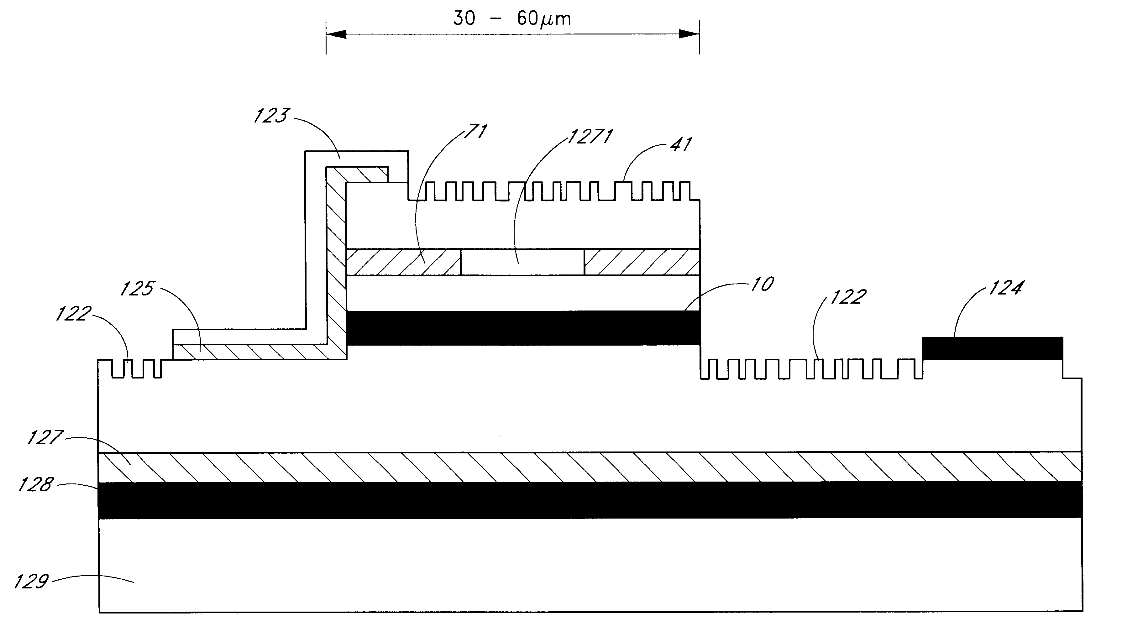
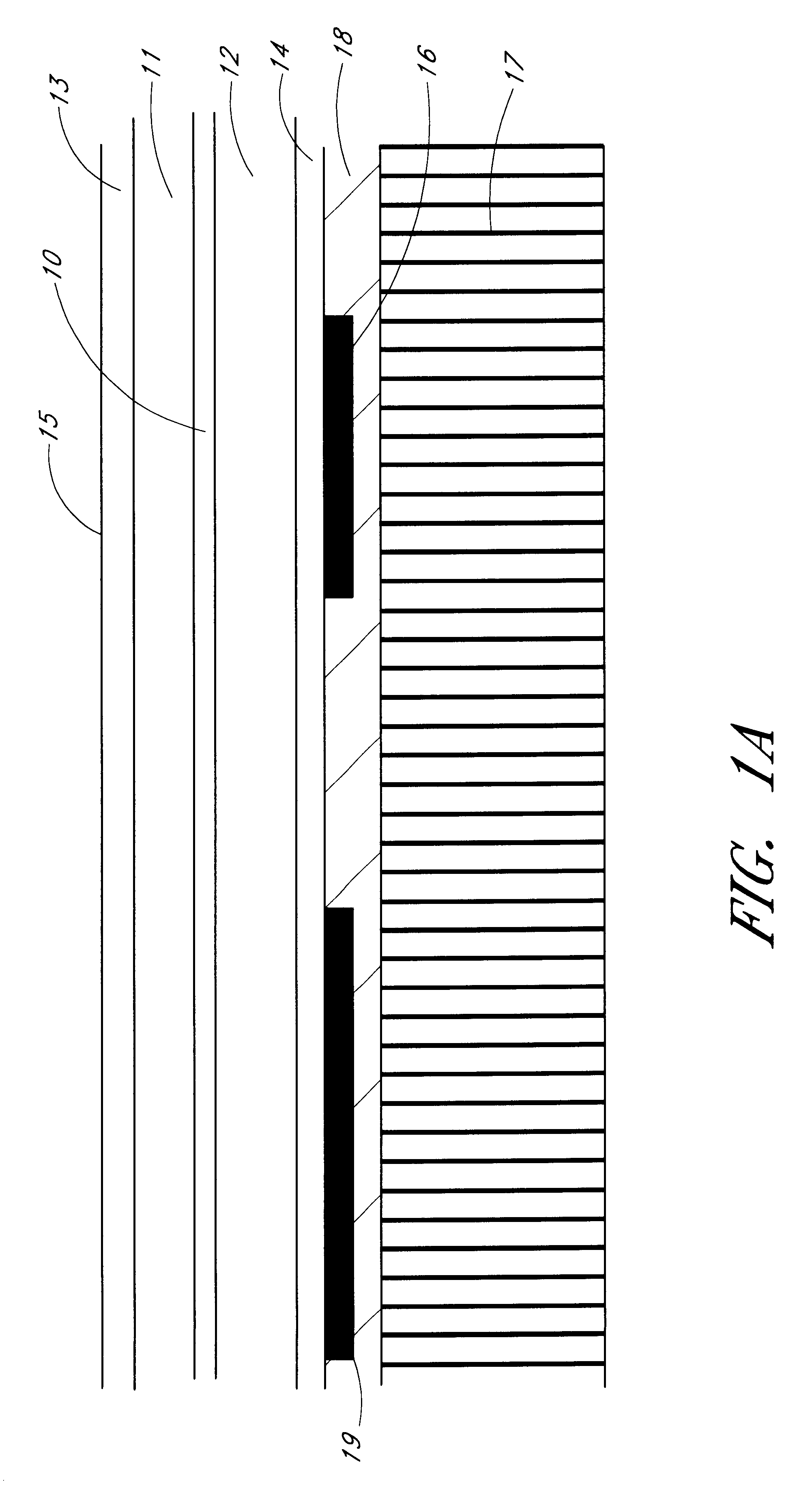
FIG. 1a shows the layer structure of a light-emitting diode (LED) according to an embodiment of a device of the present invention. This layer structure will be assumed for the devices disclosed in this detailed description of the invention. A layer structure is shown and the layers are made in semiconductor material, preferably III-V semiconductor material and the different layers can be made of different semiconductors. The layers can be epitaxially grown or can be deposited on a substrate. The substrate whereon the layers are made is removed and the layer struct...


PUM


Abstract

A device for emitting radiation at a predetermined wavelength is presented. This device has a cavity with an active layer in which said radiation is generated by charge carrier recombination. The edges of the device define the region or space for radiation and/or charge carrier confinement. At least one of the edges of this cavity has a substantially random grating structure. The edge of the device has substantially random grating structure and can extend as at least one edge of a waveguide forming part of this radiation emitting device. The radiation emitting device of the present invention can have a cavity comprising a radiation confinement space that includes confinement features for the charge carriers confining the charge carriers to a subspace being smaller than the radiation confinement space within the cavity. The emitting device can comprise at least two edges forming, in cross-section, a substantially triangular shape. The angle between these two edges is smaller than 45°. At least one of the two edges has a transparent portion. the devices according to the present invention can be arranged in arrays.

Description

The present invention is related to the field of radiation emitting devices. More in particular semiconductor devices that emit light at a predetermined wavelength with a high efficiency are disclosed. A method of making such devices and applications of the devices are also disclosed.Semiconductor devices that can emit non-coherent or coherent light are known in the art. A number of publications on semiconductor based light emitters deals with Light Emitting Diodes (LEDs) or Microcavity LEDs or Microcavity Lasers or Vertical Cavity Surface Emitting Lasers. Examples of such publications are:H. De Neve, J. Blondelle, R. Baets, P. Demeester, P. Van Daele, G. Borghs, IEEE Photon. Technol. Lett. 7 287 (1995);E. F. Schubert, N. E. J. Hunt, R. J. Malik, M. Micovic, D. L. Miller, "Temperature and Modulation Characteristics of Resonant-Cavity Light-Emitting Diodes", Journal of Lightwave Technology, 14 (7), 1721-1729 (1996);T. Yamauchi and Y. Arakawa, Enhanced and inhibited spontaneous emissi...

Claims


Application Information

Patent Timeline
IPC IPC(8): G02B6/42H01L33/00H01L27/15H01L33/02H01L33/08H01L33/10H01L33/20H01L33/22H01L33/30H01L33/40H01L33/42H01L33/46H01L33/58H01L33/60H01L33/62
CPCG02B6/4249G02B6/4292H01L33/025H01L33/46H01L33/20H01L33/22H01L33/30H01L33/405G02B6/4224H01L27/156H01L33/385H01L33/08
Inventor HEREMANS, PAULKUIJK, MAARTENWINDISCH, REINERBORGHS, GUSTAAF
Owner SIGNIFY HLDG BV
Why Eureka
Try Eureka