Optical system and light fixture using the same

a technology of optical system and light fixture, applied in the field of optical devices, can solve the problems of affecting the projecting effect, insufficient and uniform mixing of light beams, etc., and achieve the effect of preventing light crosstalking, preventing light crosstalking effectively, and effectively preventing light crosstalking

Active Publication Date: 2020-04-21
GUANGZHOU HAOYANG ELECTRONICS CO LTD
View PDF7 Cites 0 Cited by
  • Summary
  • Abstract
  • Description
  • Claims
  • Application Information

AI Technical Summary

Benefits of technology

[0008]It is therefore an object of the present invention to provide an optical system that can present rich optical effects, prevent light crosstalking effectively and improve uniformity of light spots.
[0009]Another object of the present invention is to provide a light fixture that uses the optical system according to the present invention, which can prevent light crosstalking and improve uniformity of light spots.

Problems solved by technology

Therefore, three technical issues need to be considered, that are uniform mixing of light from different light sources, collimation of light after emitted through a light pipe and light crosstalking due to interaction of light beams.
A sufficient and uniform mixing of the light beam cannot be achieved simply by changing the cross-sectional shape of the light pipe or simply by rotating each light pipe at a certain angle.
Moreover, light crosstalking will occur when light beams of multiple light pipes pass through corresponding lenses, thus affecting the projecting effect.

Method used


Image

  • Optical system and light fixture using the same
  • Optical system and light fixture using the same
  • Optical system and light fixture using the same

Examples


embodiment 1

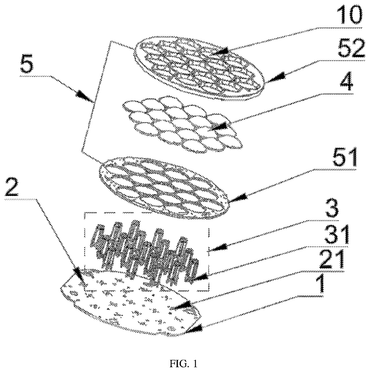
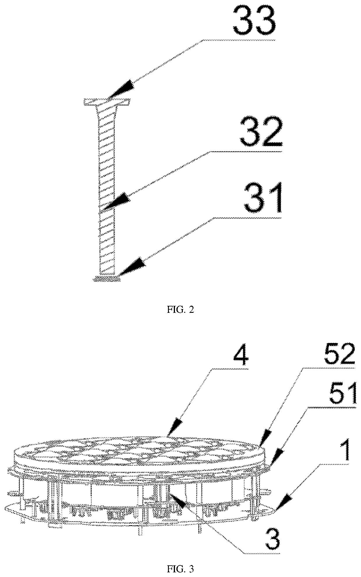
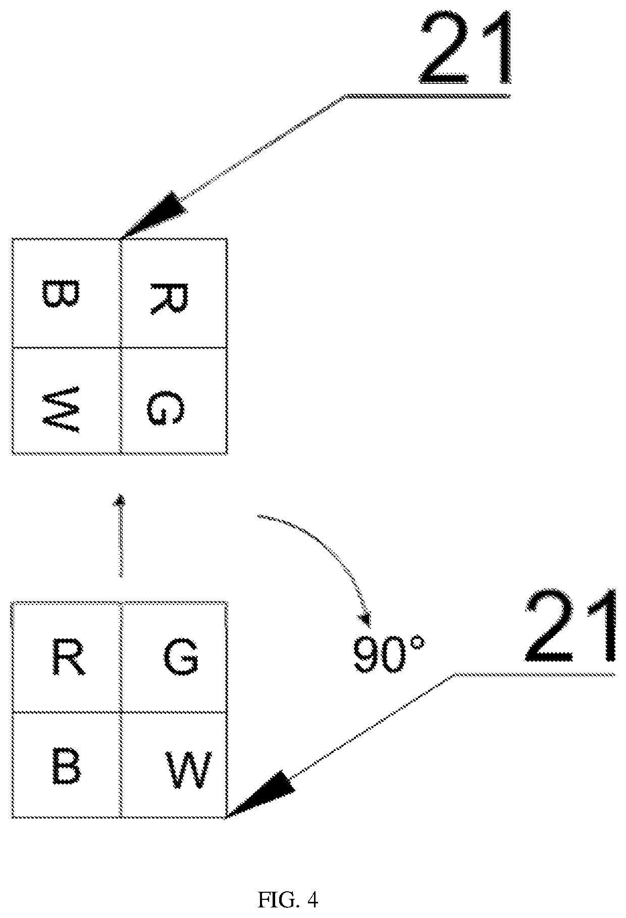
[0103]In one exemplary embodiment, the present invention discloses an optical system, as shown in FIG. 1 and FIG. 2, comprising a substrate 1, a light source 2, a light pipe 3 and an optical lens 4, wherein the light source 2 is mounted on the substrate 1 and includes multiple sets of light emitting arrays 21, corresponding to each set of the light emitting arrays 21, a light pipe 3 is arranged, which includes an input surface 31, at least one light guiding surface 32 and an output surface 33. Light emitted from the light emitting arrays 21 can enter through the input surface 31 of the light pipe 3 and is outputted from the output surface 33 through light homogenizing treatment by the light guiding surface 32, such light out of the light pipe forming a light beam and being emitted via the optical lens 4. Additionally, the optical system further comprises a honeycomb-like cover 5 that includes multiple through holes 10 sleeved on the lens of the optical lens 4. A cross section of the...

embodiment 2

[0137]As shown in FIG. 7, this embodiment is different from embodiment 1 in that the deflection angle of at least one set light emitting arrays 21 with respect to at least one set of other light emitting arrays 21 is 180°.

embodiment 3

[0138]As shown in FIG. 8, this embodiment is different from embodiment 1 in that the deflection angle of the at least one set light emitting arrays 21 with respect to at least one set of other light emitting arrays 21 is 270°.


PUM

PropertyMeasurementUnit
axial heightaaaaaaaaaa
deflection angleaaaaaaaaaa

Abstract

The present invention provides an optical system and a light fixture using the optical system, the optical system comprising a substrate, a light source mounted on the substrate and including multiple sets of light emitting arrays, a light pipe arranged corresponding to each set of the light emitting arrays, including an input surface, at least one light guiding surface and an output surface, and an optical lens. Additionally, the optical system further comprises honeycomb-like cover including multiple through holes, each through hole sleeved on each lens of the optical lens, a cross section of the through hole matching with a maximum cross section of the lens of the optical lens, and an overall shape of the through holes arranged on the honeycomb-like cover matching with that of the light source arranged on the substrate. On such configuration, uniform light spots can be achieved and light crosstalking can be effectively prevented.

Description

CROSS-REFERENCE TO RELATED APPLICATIONS[0001]The present application claims priority from Chinese Patent Application Nos. 201810421898.8, filed May 4, 2018, and 201810443393.1, filed May 10, 2018, the disclosures of which are hereby incorporated herein by reference.TECHNICAL FIELD[0002]The present invention relates to an optical device, particularly relates to an optical system that are used for mixing light, homogenizing light and are capable of preventing light crosstalking, and also relates to a light fixture using the same.BACKGROUND OF THE INVENTION[0003]Compared with a fluorescent lamp, an LED light source, known as a new generation of light source that is energy-saving and environment-friendly, has the advantage of smaller size, lower energy consumption, longer service life and higher lighting efficiency. At present, there are many fluorescent tubes made of LED light sources on the market to replace common fluorescent tubes. The fluorescent tubes that use LED as light sources...

Claims


Application Information

Patent Timeline
Patent Type & Authority Patents(United States)
IPC IPC(8): G02B27/09F21V9/40F21V8/00F21Y115/10
CPCG02B27/0961G02B6/0005F21V9/40G02B27/0994F21Y2115/10F21V5/04F21V19/001F21V2200/00F21K9/20F21V5/007F21V13/02F21W2131/406F21Y2105/18F21Y2113/13G02B3/0056G02B3/0075G02B19/0028G02B19/0066G02B27/0018
Inventor JIANG, WEIKAI
Owner GUANGZHOU HAOYANG ELECTRONICS CO LTD
Why Eureka
Try Eureka