Preliminary Products for Light Protection Devices with High-Precision Optics for Glare-Free Light Deflection

Pending Publication Date: 2022-11-17
KOESTER HELMUT
View PDF0 Cites 0 Cited by
  • Summary
  • Abstract
  • Description
  • Claims
  • Application Information

AI Technical Summary

Problems solved by technology

A disadvantage of this structure is that each individual mirror prism has a different contour and in addition, for each slat width, a dedicated surface has to be developed, for which each mirror prism has to be shaped differently.
The disadvantage of the methods explained therein is the inorganic sol-gel coating and the sawtooth-like prism contour.
This requires extremely complex tool geometries in order to form Fresnel optics.
In addition, the explained methods for producing prisms with sol-gel have proved not to be successful.
Hitherto it has not been technically possible to reproduce the contour illustrated in FIG. 9 on a slat using a sol-gel, nor has sufficient adhesion been achieved in respect of the UV-curing sol-gel coatings adhering to the metallic slats, nor has it been possible to achieve sufficient precision and sharpness of edges of the prism vertices by means of the UV-curing, nor have the slats been able to be coiled after application of the sol-gel layer without producing microfractures in the glass-hard coating.
Infiltrations take place through the microfractures in the glass-hard sol-gel layers and result in detachments.
However, it lacks any teaching of how the skilled worker has to curve the slats in relation to the slat width and in relation to the inclination of the prism sidewalls.
Moreover, it is not known how the flat, prism-stru

Method used


Image

  • Preliminary Products for Light Protection Devices with High-Precision Optics for Glare-Free Light Deflection
  • Preliminary Products for Light Protection Devices with High-Precision Optics for Glare-Free Light Deflection
  • Preliminary Products for Light Protection Devices with High-Precision Optics for Glare-Free Light Deflection

Examples


Embodiment Construction

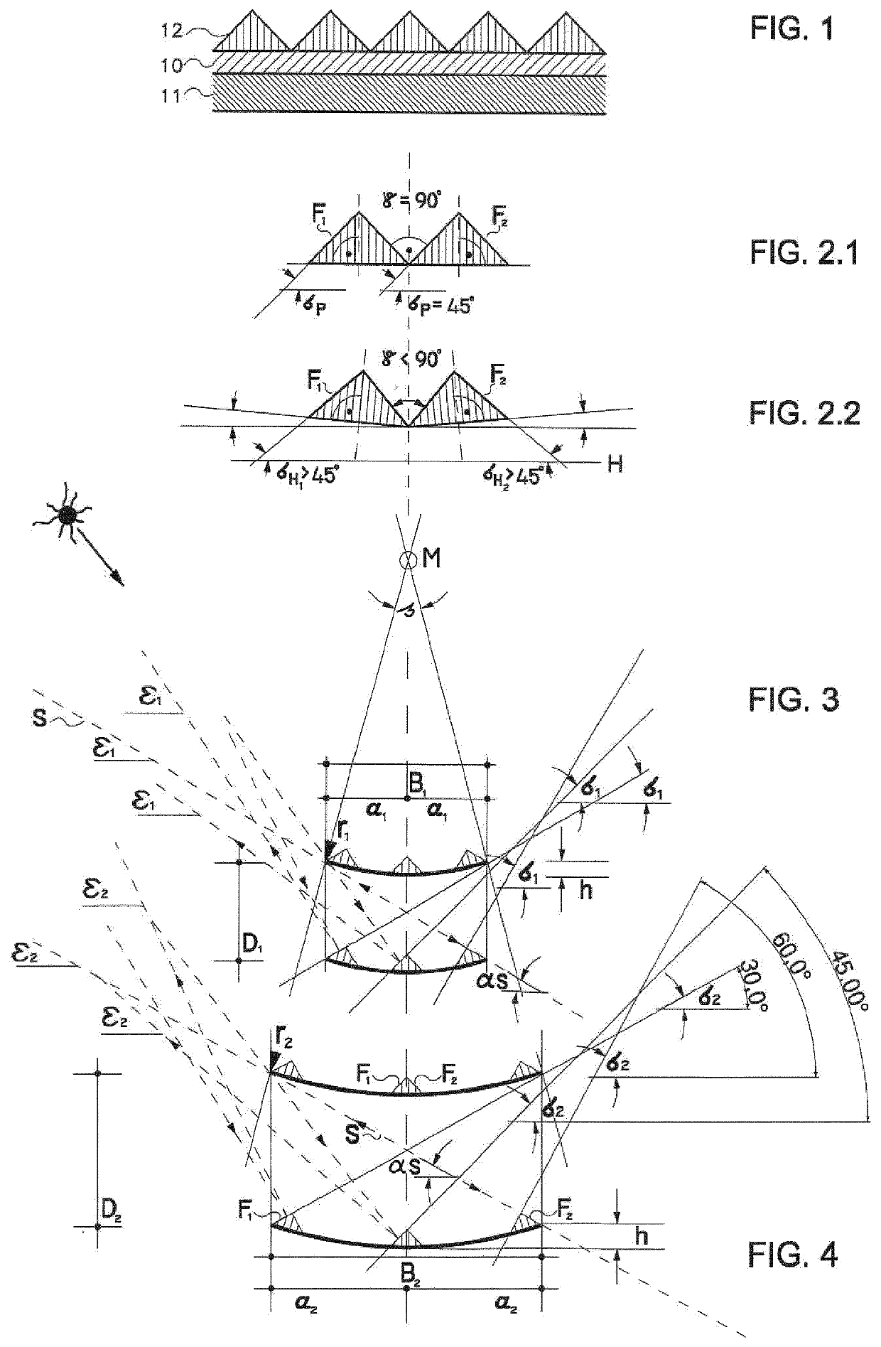
[0044]FIG. 1 shows a preliminary product in cross section, consisting of a main body 11 and the triangular grooves 12. The grooves 12 are situated on or in a carrier film 10 combined with the slat body 11. The grooved furrows are either imprinted or embossed and reflectively coated / metallized in the preliminary product. The term preliminary product relates to a web-type material with any desired working width. The preliminary product can be split into narrow strips. The end product of a focusing slat arises as a result of curvature of the split-off preliminary product. The individual work steps are preferably carried out from the coil.

[0045]In the case of a film support, the bond between slats 11 and carrier film 10 is effected by adhesive bonding, preferably by means of hot melt adhesives in a continuous method between two heated rollers. The continuous method works from coil to coil. The main body 11 consists e.g. of aluminium or steel or else of plastic or wood veneer and can als...


PUM


Abstract

The invention relates to a planar preliminary product for producing focusing light-directing slats having a top side and an underside. The top side and the underside are the largest sides in terms of area. The top side has a groove structure having parallel grooves and ridges in a longitudinal direction and having a multiplicity of sidewalls F1 and F2. A respective pair of sidewalls F1 and F2 forms a common ridge projecting on the top side. The sidewalls F1 and F2 are in each case at an angle with respect to one another which is at least approximately constant along the transverse direction and longitudinal direction of the groove structure. The top side has an overall contour defined by the vertices of the ridges. The sidewalls F1 and F2 of adjacent pairs are at an angle γ with respect to one another. The sidewalls F1 and F2 are symmetrical with respect to one another in relation to an area of symmetry, which is oriented at right angles with respect to the overall contour and is arranged at the location lying in the centre between the sidewalls F1 and F2. The angle γ between all pairs of sidewalls F1 and F2 is at least approximately constant. The sidewalls have a surface, which surfaces specularly reflect light substantially according to the law of reflection that angle of incidence is equal to angle of reflection.

Description

FIELD OF THE INVENTION[0001]The invention relates to a planar preliminary product for producing focusing light directing slats having a top side and an underside. The top side and the underside are the largest sides in terms of area. The top side has a groove structure having parallel grooves and ridges in a longitudinal direction and having a multiplicity of sidewalls F1 and F2. A respective pair of sidewalls F1 and F2 forms a common ridge projecting on the top side. The sidewalls F1 and F2 are in each case at an angle with respect to one another which is at least approximately constant along the transverse direction and longitudinal direction of the groove structure. The top side has an overall contour defined by the vertices of the ridges. The sidewalls F1 and F2 of adjacent pairs are at an angle γ with respect to one another.BACKGROUND OF THE INVENTION[0002]DE 10 2014 005 480 presents a preliminary product of a prism embossing structure on a flat, rolled strip, which is brought ...

Claims


Application Information

Patent Timeline
IPC IPC(8): E06B9/386F21S11/00
CPCE06B9/386F21S11/007E06B2009/2417F21S11/00E06B9/28
Inventor KOESTER, HELMUT
Owner KOESTER HELMUT
Why Eureka
Try Eureka