Thermally response controlled gap seal device

a technology of gap seals and thermal response, which is applied in the direction of engine seals, leakage prevention, other manufacturing equipment/tools, etc., can solve the problems of increased leakage and insufficient responsiveness of shrink band, and achieve the effect of controlling cooling and shrinking the ring

Active Publication Date: 2013-10-31
PRATT & WHITNEY CANADA CORP
View PDF13 Cites 32 Cited by
  • Summary
  • Abstract
  • Description
  • Claims
  • Application Information

AI Technical Summary

Benefits of technology

[0004]In one aspect, there is provided a controlled gap seal device adapted to surround a shaft, the device comprising: an annular seal element; a ring positioned on an outer surface of the seal element, the ring adapted to modify a diametrical dimension of the seal element by thermally expanding/contracting as a function of temperature variations; and a housing assembly ha

Problems solved by technology

In some transient temperature excursions, the shrink band may not be sufficiently responsive as it may not be directly exposed to surro

Method used


Image

  • Thermally response controlled gap seal device
  • Thermally response controlled gap seal device
  • Thermally response controlled gap seal device

Examples


Embodiment Construction

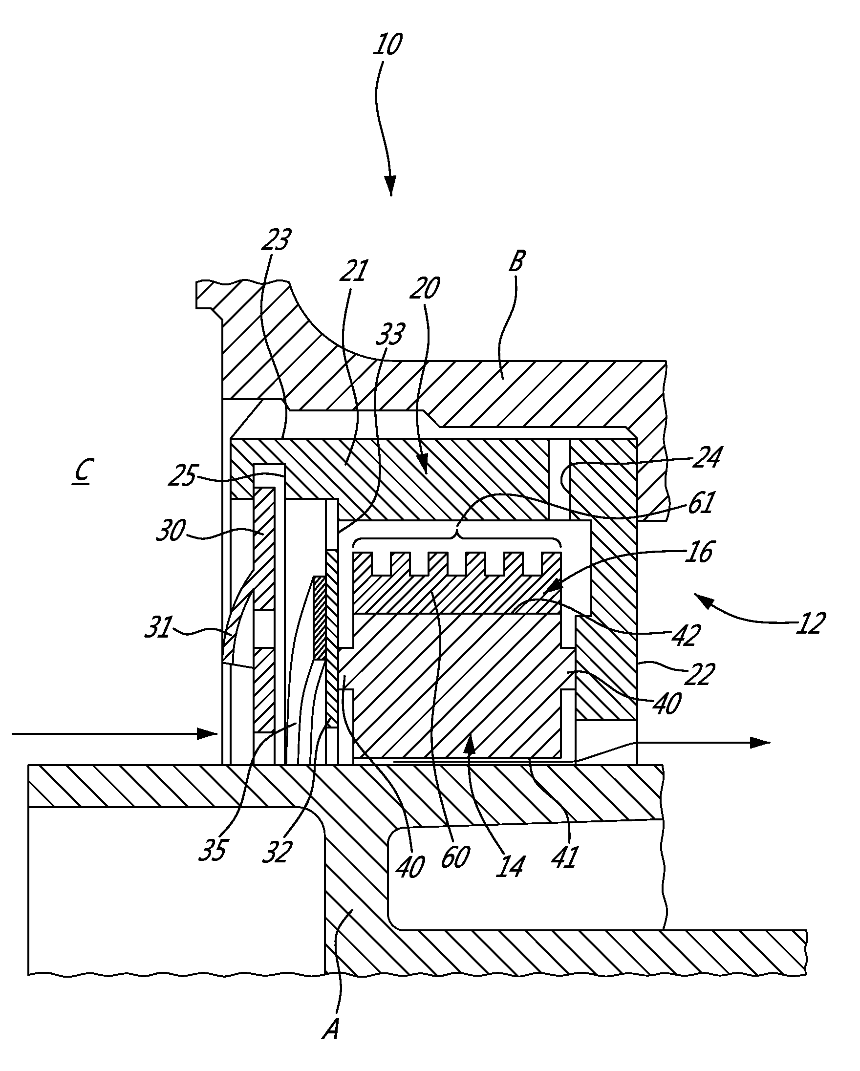
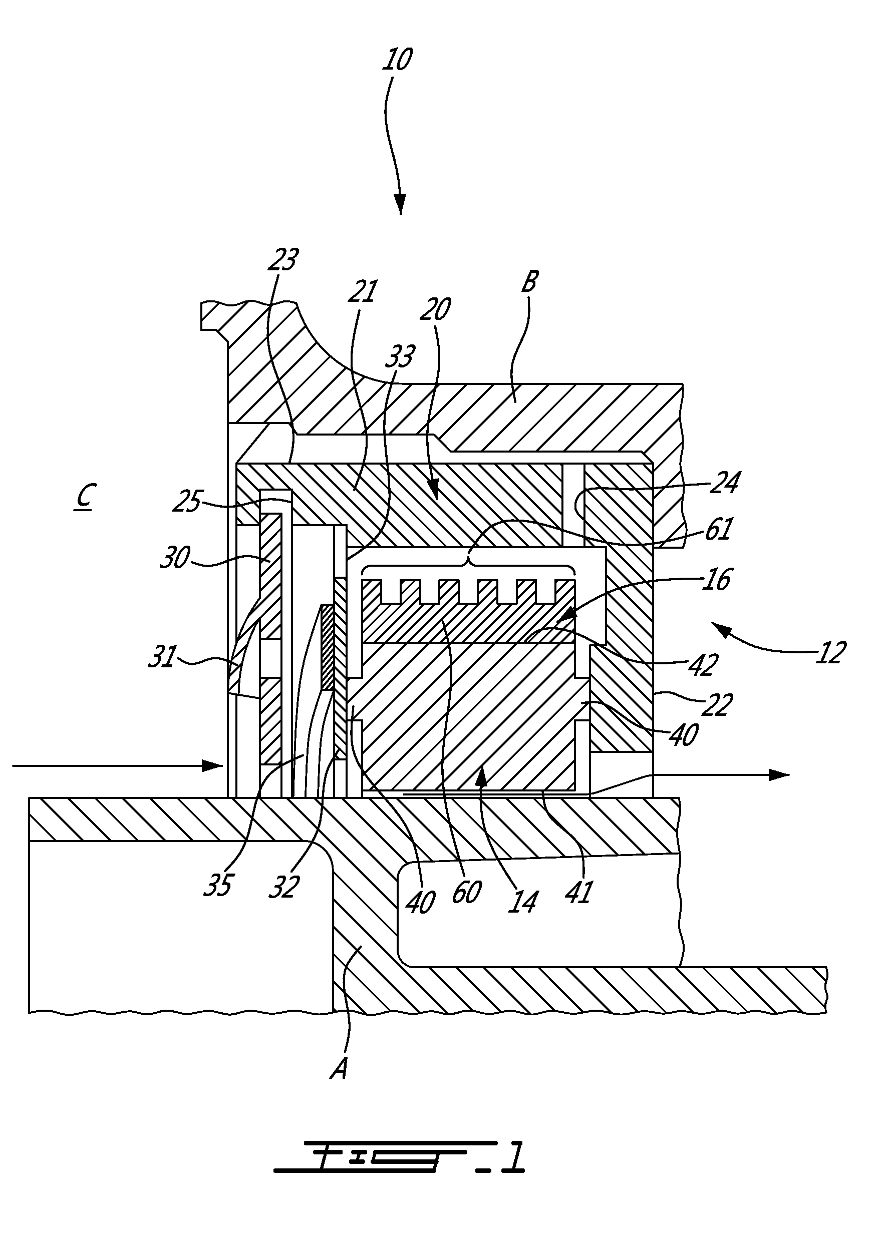
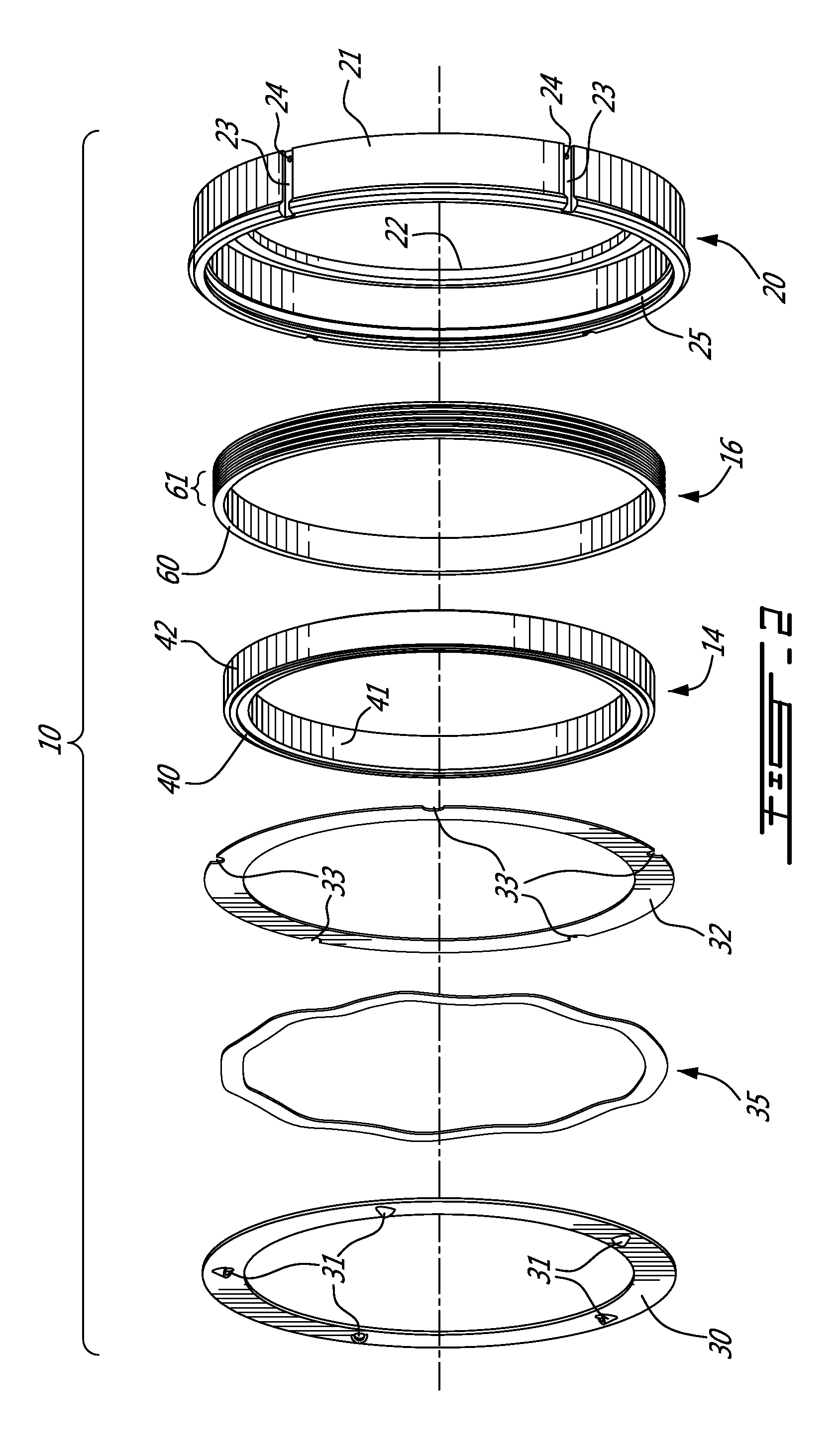
[0011]Referring to FIGS. 1 to 3, there is illustrated a thermally responsive controlled gap seal device 10 in accordance with the present disclosure. The thermally responsive controlled gap seal device 10 is used between a shaft and a structural component, such as seal runner A and bearing housing B. According to an embodiment, the thermally responsive controlled gap seal device 10 may be adjacent to a bearing (part of which is the bearing housing B) supporting the seal runner A, with the seal runner A rotating about its longitudinal axis. The thermally responsive controlled gap seal device 10 is positioned about the seal runner A to reduce the amount of air / gases reaching the bearing. A gap is defined between the thermally responsive controlled gap seal device 10, such that the thermally responsive controlled gap seal device 10 generally remains stationary while the shaft rotates.

[0012]The thermally responsive controlled gap seal device 10 may have a housing assembly 12, a seal 14 ...


PUM

PropertyMeasurementUnit
Temperatureaaaaaaaaaa
Flow rateaaaaaaaaaa
Diameteraaaaaaaaaa

Abstract

A controlled gap seal device is adapted to surround a shaft with an annular seal element. A ring is positioned on an outer surface of the seal element, the ring adapted to modify a diametrical dimension of the seal element by thermally expanding/contracting as a function of temperature variations. A housing assembly has an interior enclosing the seal element and the ring, with the seal configured to be generally stationary in the interior. The housing assembly has an air inlet and air outlet in fluid communication with a surrounding environment for directing a flow of gas from the surrounding environment onto the ring to controllably cool and shrink the ring. A method for modifying a diameter of a controlled gap seal relative to the shaft is also provided.

Description

TECHNICAL FIELD[0001]The present application relates to gas turbine engines, and more particularly to controlled gap seals used in gas turbine engines.BACKGROUND OF THE ART[0002]Controlled gap seals, such as carbon controlled gap seals, are commonly used in gas turbine engines, generally to seal bearing compartments. These seals are designed to run with a few thousands of an inch of clearance between a stationary carbon element and a rotating seal runner or shaft. As the temperature of the bearing area heats and cools, the seal is designed to react to temperature variations and keep the seal clearance or gap relatively constant. This may be done by having a shrink band on the carbon element. The shrink band is a metal ring that is in a tight-fitting engagement onto the carbon element. The shrink band is heated and cooled by the surrounding air, thus controlling the expansion and contraction of the carbon element. In some transient temperature excursions, the shrink band may not be s...

Claims


Application Information

Patent Timeline
IPC IPC(8): F01D11/02B23P17/04
CPCF01D11/02F01D11/003Y10T29/49716F16J15/346F16J15/441F01D11/025F16J15/164F16J15/445F16J15/443
Inventor KOSTKA, RICHARD A.CARPENTER, DEANURAC, TIBORLOGAN, ADAMGREY, AARON
Owner PRATT & WHITNEY CANADA CORP
Why Eureka
Try Eureka