Stereo display
a display and stereo technology, applied in the field of display, can solve the problems of unsatisfactory stereo image viewed by users, and achieve the effect of improving the stereo display effect of the display
- Summary
- Abstract
- Description
- Claims
- Application Information
AI Technical Summary
Benefits of technology
Problems solved by technology
Method used
Image
Examples
first embodiment
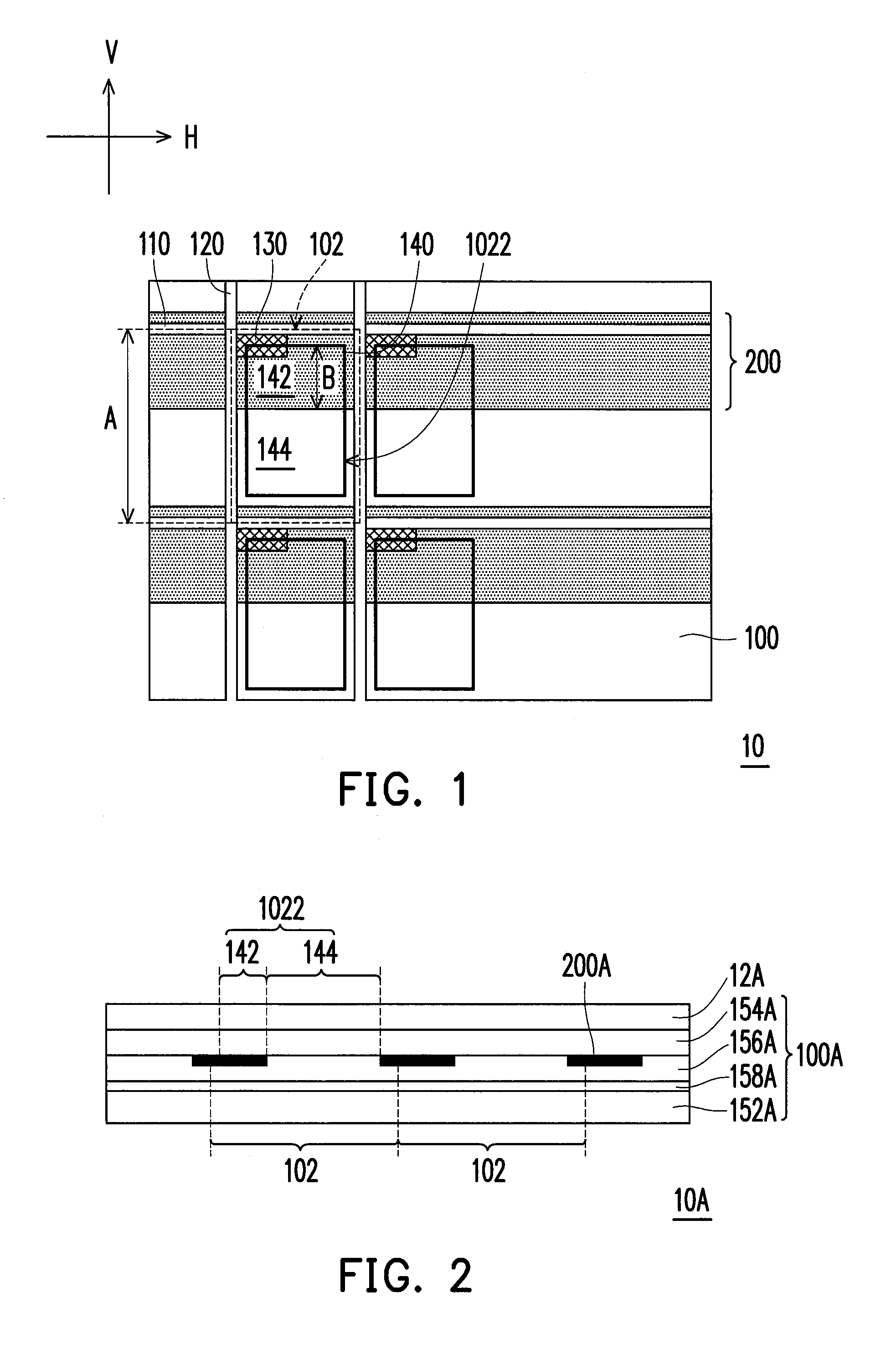
[0040]FIG. 2 illustrates a cross-sectional design of a stereo display according to the invention. Referring to FIG. 2, the stereo display 10A includes a display panel 100A, a light shieldable element 200A and an optical device 12A. The optical device 12A is disposed in front of the display panel 100A, which is, for example, a parallax barrier, a switchable parallax barrier, a phase retarder, or a switchable phase retarder, etc., so that the display light of the display panel 100A can be correspondingly received by the left eye or the right eye of the user. In an example, the left and right eye image pixels distributed alternatively in the display panel 100A may simultaneously display, and the optical device 12A (for example, a parallax barrier film) disposed in front of the display panel 100A limits a propagating path of the light. In this way, the viewer may have a stereo visual experience while locates at a setting area the light of the left image pixels and the light of the right...
second embodiment
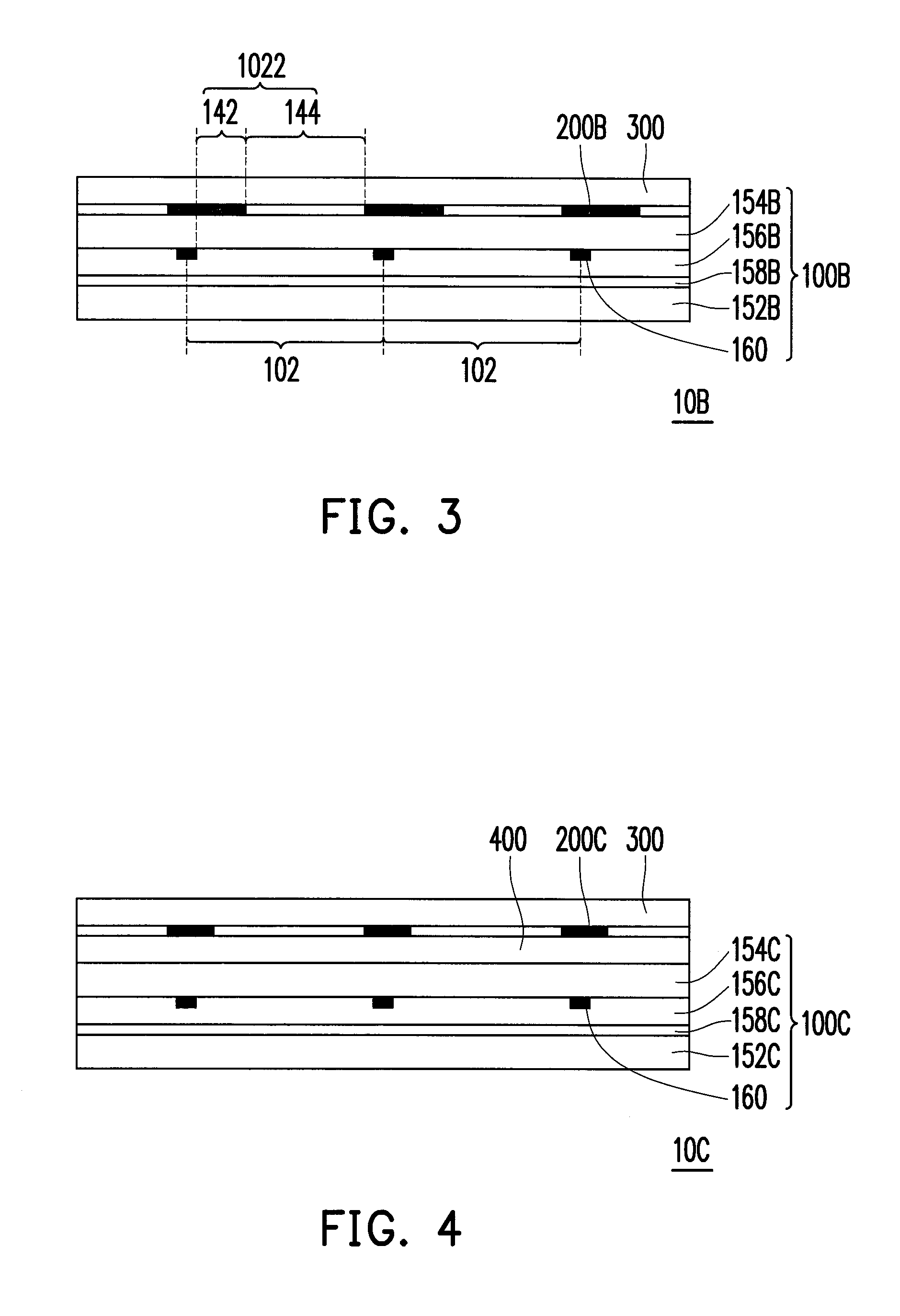
[0044]FIG. 3 illustrates a cross-sectional design of a stereo display according to the invention. Referring to FIG. 3, the stereo display 10B includes a display panel 100B, a light shieldable element 200B and a transparent substrate 300. The transparent substrate 300 is disposed in front of the display panel 100B. Moreover, the light shieldable element 200B is disposed between an outer surface of the substrate 154B and the transparent substrate 300. The transparent substrate 300 and the light shieldable element 200B may construct an optical device 12A as that shown in FIG. 2, which is, for example, a parallax barrier, so that the display light of the display panel 100B can be correspondingly received by the left eye or the right eye of the user under a shielding function of the light shieldable element 200B. Namely, the light having the left and right eye image pixels distributed alternatively in the display panel 100B may simultaneously display, and the optical device (for example,...
third embodiment
[0048]FIG. 4 illustrates a cross-sectional design of a stereo display according to the invention. Referring to FIG. 4, the stereo display 10C includes a display panel 100C, a light shieldable element 200C and a pair of transparent substrates 300 and 400. The transparent substrates 300 and 400 are disposed in front of the display panel 100C. Moreover, the light shieldable element 200C is disposed between the transparent substrates 300 and 400. Now, the pair of the substrates 300 and 400 and the light shieldable element 200C sandwiched between the two substrates 300 and 400 form the optical device 12A as that shown in FIG. 2, which is, for example, a parallax barrier, so that the display light of the display panel 100C can be correspondingly received by the left eye or the right eye of the user under a shielding function provided by the light shieldable element 200C. Namely, the light having the left and right eye image pixels distributed alternatively in the display panel 100C may si...
PUM
| Property | Measurement | Unit |
|---|---|---|
| length | aaaaa | aaaaa |
| length percentage | aaaaa | aaaaa |
| transparent | aaaaa | aaaaa |
Abstract
Description
Claims
Application Information
 - R&D
- Intellectual Property
- Life Sciences
- Materials
- Tech Scout
- Unparalleled Data Quality
- Higher Quality Content
- 60% Fewer Hallucinations
Browse by: Latest US Patents, China's latest patents, Technical Efficacy Thesaurus, Application Domain, Technology Topic, Popular Technical Reports.
© 2025 PatSnap. All rights reserved.Legal|Privacy policy|Modern Slavery Act Transparency Statement|Sitemap|About US| Contact US: help@patsnap.com


