Automatic detection method of video wall arrangement and video wall system using the same

a detection method and video wall technology, applied in the field of video walls, can solve problems such as difficult installation of video wall systems

Active Publication Date: 2013-11-07
SAMSUNG ELECTRONICS CO LTD
View PDF5 Cites 21 Cited by
  • Summary
  • Abstract
  • Description
  • Claims
  • Application Information

AI Technical Summary

Benefits of technology

[0027]According to an aspect of another exemplary embodiment, there is provided an automatic detection method of an arrangement of a video wall including a plurality of monitors, the automatic detection method including: calling, by a control computer, identification information of a first monitor, from among the plurality of monitors; receiving, by the control computer, a detecting signal from a second monitor, from among the plurality of monitors, that does not correspond to the called identification information, the detecting signal indicating a received direction of a response signal received by the second monitor from the first monitor in response to the calling; and determining an arrangement of the plurality of monitors according to the received detecting signal.
[0028]According to an aspect of another exemplary embodiment, there is provided an automatic detection method of an arrangement of a video wall including a plurality of monitors, the automatic detection method including: receiving, by a first monitor from a control computer, called identification information called by the control computer; in response to the called identification information corresponding to the first monitor, from among the plurality of monitors, sending, by the first monitor, a first response signal indicating that the called identification information corresponds to the first monitor; in response to the called identification information not corresponding to the first monitor, not sending, by the first monitor, the first response signal; and in response to receiving a second response signal from a second monitor, sending, to the control computer by the first monitor, a detecting signal indicating a received direction of the response signal by the first monitor from the second monitor, wherein the second response signal indicates that the called identification information corresponds to the second monitor.

Problems solved by technology

Therefore, installation of the video wall system is not easy.

Method used


Image

  • Automatic detection method of video wall arrangement and video wall system using the same
  • Automatic detection method of video wall arrangement and video wall system using the same
  • Automatic detection method of video wall arrangement and video wall system using the same

Examples


Embodiment Construction

[0042]Hereinafter, exemplary embodiments will be described in detail with reference to the accompanying drawings.

[0043]The matters defined herein, such as a detailed construction and elements thereof, are provided to assist in a comprehensive understanding of this description. Thus, it is apparent that exemplary embodiments may be carried out without those defined matters. Also, well-known functions or constructions are omitted to provide a clear and concise description of exemplary embodiments. Further, dimensions of various elements in the accompanying drawings may be arbitrarily increased or decreased for assisting in a comprehensive understanding.

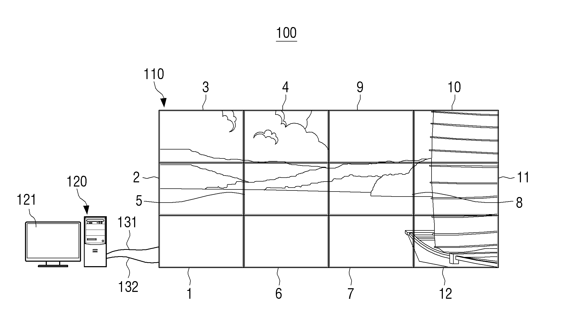
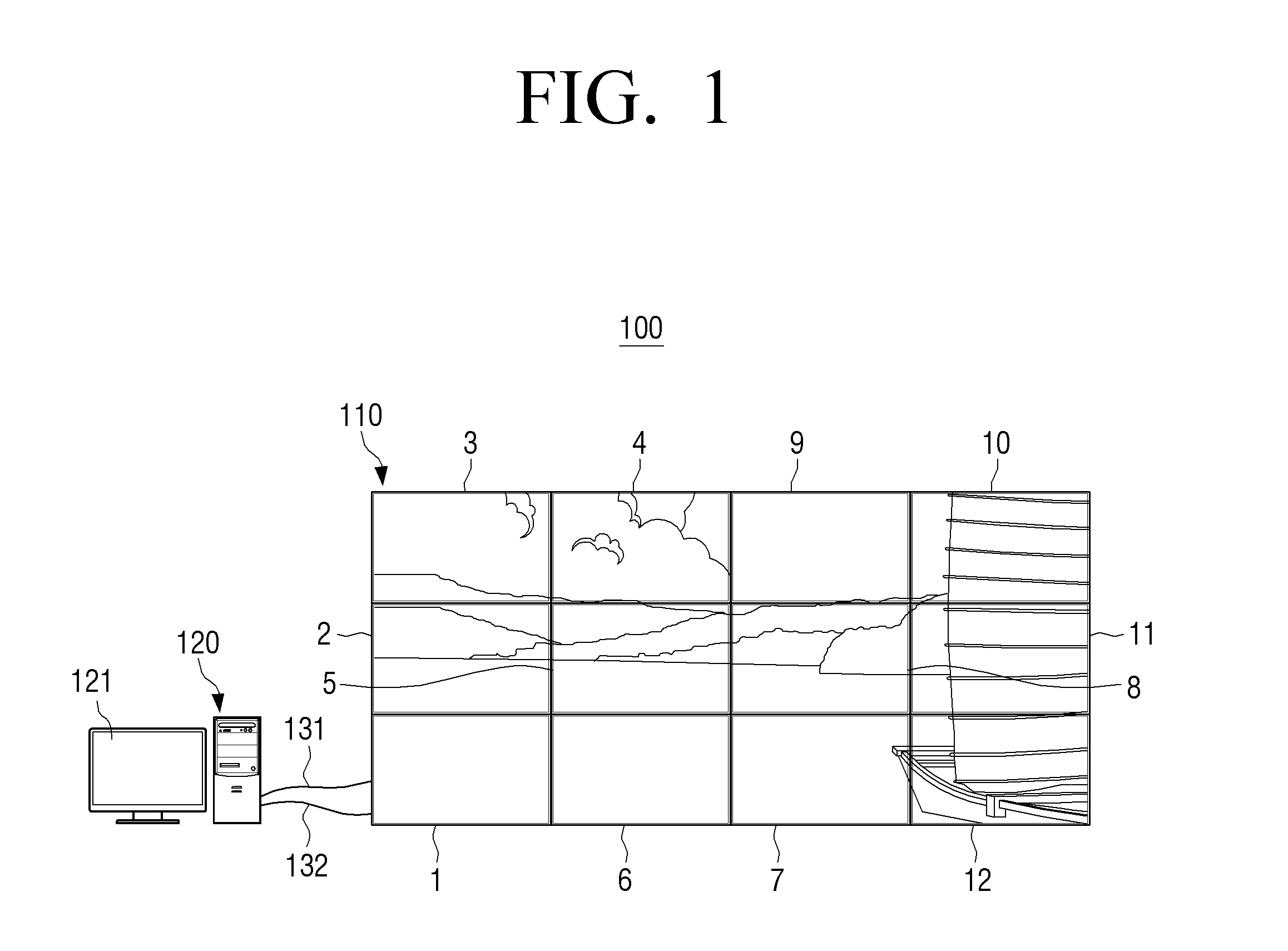
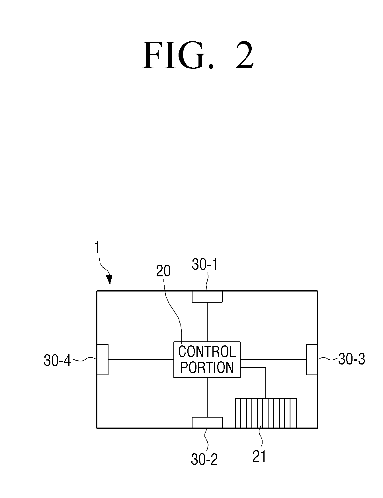
[0044]FIG. 1 is a front view schematically illustrating a video wall system according to an exemplary embodiment. FIG. 2 is a view schematically illustrating an inner structure of a monitor of a video wall system according to an exemplary embodiment.

[0045]Referring to FIG. 1, a video wall system 100 according to an exemplary embodiment ...


PUM


Abstract

An automatic detection method of an arrangement of a video wall including a plurality of monitors and a video wall system are provided. The method includes: calling, by a control computer, identification information of a first monitor of the plurality of monitors; sending, by the first monitor, a response signal to the control computer and sending, by a second monitor which does not correspond to the called identification information, a detecting signal including a received direction of the response signal to the control computer; and receiving, by the control computer, the detecting signal, and determining the arrangement of the plurality of monitors according to the received detecting signal.

Description

CROSS-REFERENCE TO RELATED APPLICATION[0001]This application claims priority under 35 U.S.C. §119(a) from Korean Patent Application No. 10-2012-0047737, filed May 3, 2012 in the Korean Intellectual Property Office, the disclosure of which is incorporated herein by reference in its entirety.BACKGROUND[0002]1. Field[0003]Apparatuses and methods consistent with exemplary embodiments relate to a video wall system including a plurality of monitors and, more particularly, to an automatic detection method of a video wall arrangement which can automatically detect arrangement and identification numbers of a plurality of monitors of a video wall and a video wall system using the automatic detection method.[0004]2. Description of the Related Art[0005]Generally, a video wall refers to an apparatus including a plurality of monitors which are arranged on a plane and respectively display different portions of one image so that the plurality of monitors can work as one monitor having a large-sized...

Claims


Application Information

Patent Timeline
Patent Type & Authority Applications(United States)
IPC IPC(8): G06F3/14
CPCG06F3/1446G06F3/147G09G2360/04G09G2370/04G09G2370/042G06F3/14G06F13/14G09F9/00
Inventor SEO, JEONG-RYEOLKIM, YOUNG-KOOKKIM, HYUN-AHPARK, JI-EUNSON, JIN-HOLEE, SEUNG-HUNCHOI, KI-SEOKCHOI, WON-YONGCHOI, YUN-SUK
Owner SAMSUNG ELECTRONICS CO LTD
Why Eureka
Try Eureka