Methods and systems for engine cranking

a technology of engine cranking and cranking gear, which is applied in the direction of engine-driven generators, machines/engines, vehicle sub-unit features, etc., can solve the problems of limited use of electric machines, low power output capacity of electric machines, and inability to accelerate beyond vehicle creep speed without engine assistance, etc., to achieve the effect of extending the torque range of the driver demand of the driveline integrated starter/generator, reducing power output capacity, and reducing power consumption

Active Publication Date: 2013-11-07
FORD GLOBAL TECH LLC
View PDF10 Cites 80 Cited by
  • Summary
  • Abstract
  • Description
  • Claims
  • Application Information

AI Technical Summary

Benefits of technology

[0005]In other words, the engine may be started by two electric machines during different conditions so that one electric machine may help to provide torque to a vehicle driveline over a broader range of conditions while the other electric machine may have a specific function of starting the engine. For example, a driveline integrated starter / generator may start the engine and provide torque to a driveline during low driver demand torque conditions. Further, the driveline integrated starter / generator may supply torque to the driveline at higher drive demand torque conditions while a lower power output capacity electric machine starts the engine. The lower power capacity electric machine allows the driveline integrated starter / generator to provide driveline torque over a broader driver demand torque range. In this way, a smaller driveline integrated starter / generator may provide a driveline torque function that heretofore required a larger electric machine.
[0006]The present description may provide several advantages. Specifically, the approach may extend a driver demand torque range of a driveline integrated starter / generator. Further, the approach may improve engine starting by allowing the engine to accelerate to a speed of the driveline integrated starter / generator before a driveline disconnect clutch is closed.

Problems solved by technology

In some vehicle designs, the engine may have significantly higher output capacity than the electric machine due to packaging and weight constraints.
However, the electric machine may not be useful to accelerate beyond vehicle creep speed without assistance from the engine since the electric machine is tasked with accelerating the vehicle and starting the engine.
Consequently, the electric machine may provide limited use beyond starting the engine.
Further, the driveline integrated starter / generator may supply torque to the driveline at higher drive demand torque conditions while a lower power output capacity electric machine starts the engine.

Method used


Image

  • Methods and systems for engine cranking
  • Methods and systems for engine cranking
  • Methods and systems for engine cranking

Examples


Embodiment Construction

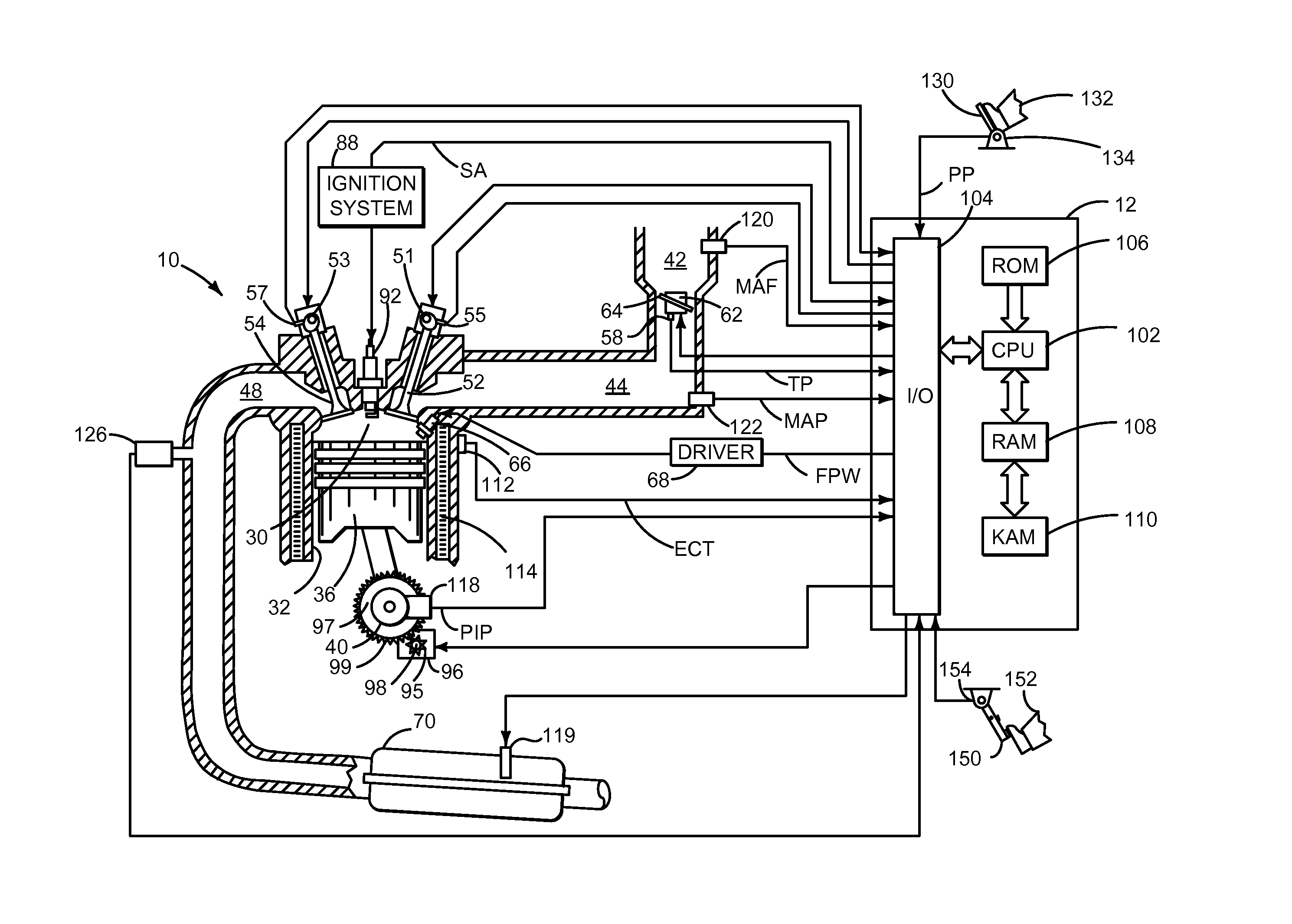
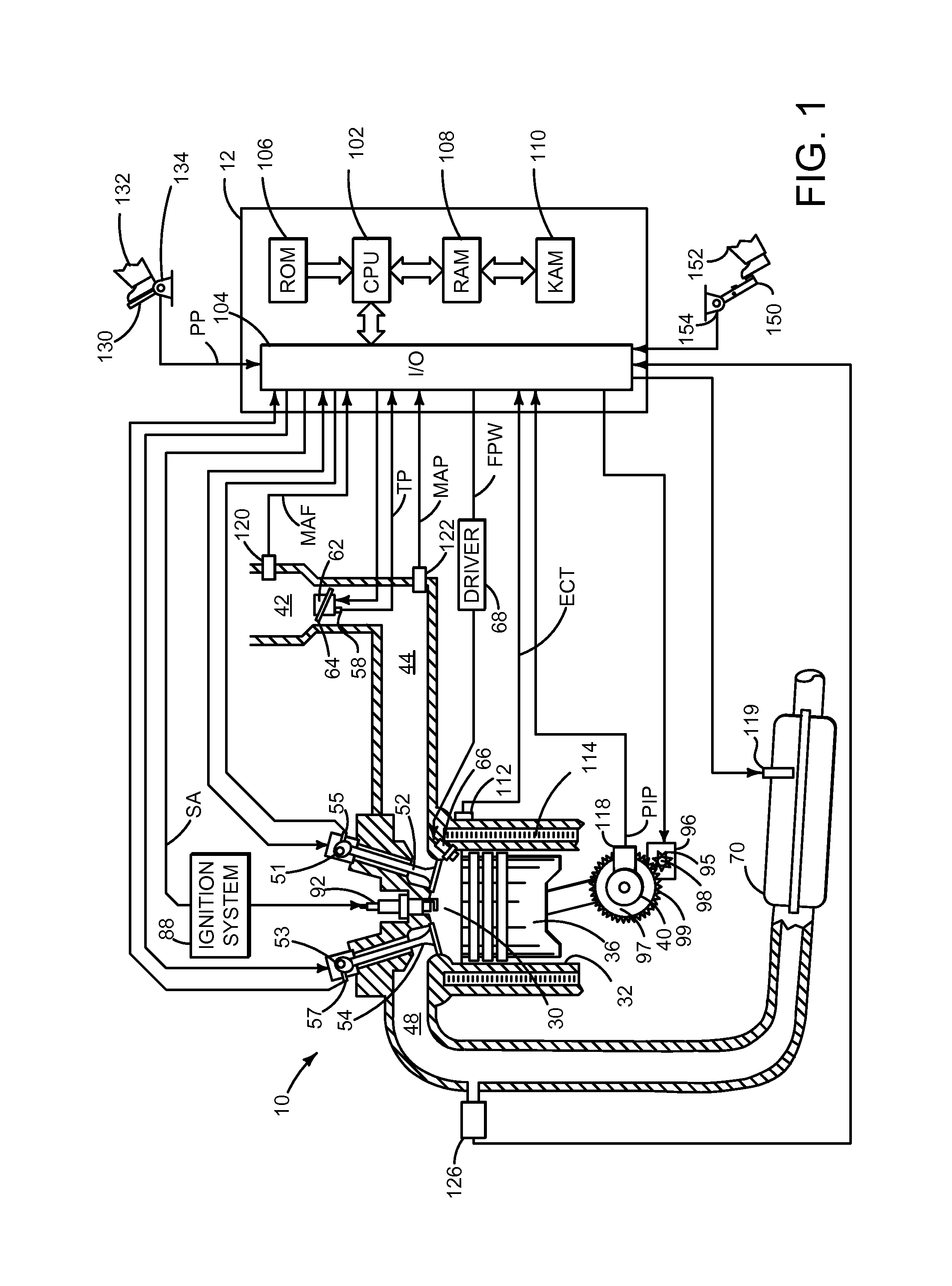
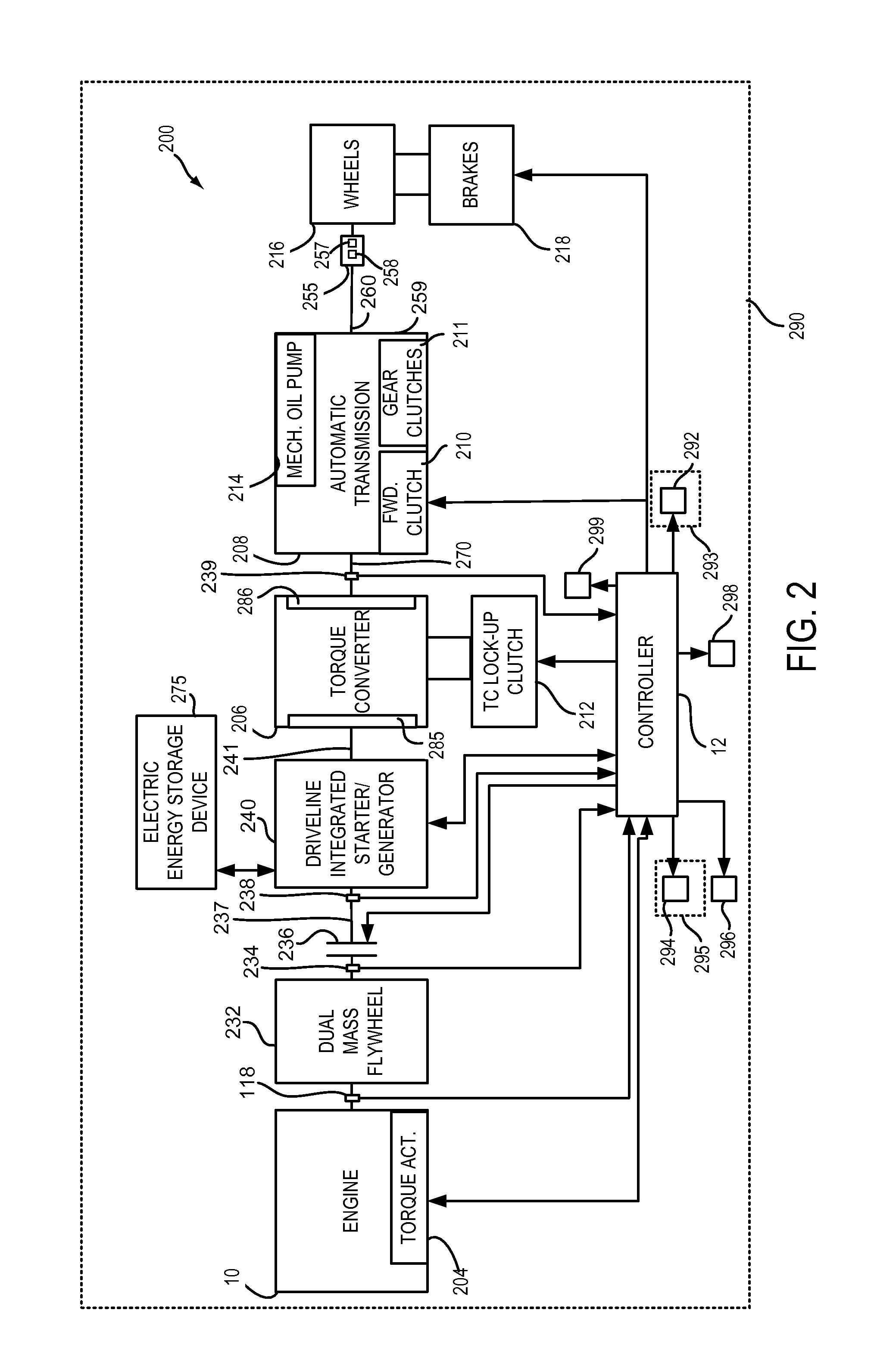
[0026]The present description is related to controlling a driveline of a hybrid vehicle. The hybrid vehicle may include an engine and electric machine as shown in FIGS. 1-3. The engine may be operated with or without a driveline integrated starter / generator (e.g., an electric machine or motor that may be abbreviated DISG) during vehicle operation. The driveline integrated starter / generator is integrated into the driveline on the same axis as the engine crankshaft and rotates whenever the torque converter impeller rotates. Further, the DISG may not be selectively engaged or disengaged with the driveline. Rather, the DISG is an integral part of the driveline. Further still, the DISG may be operated with or without operating the engine. The mass and inertia of the DISG remain with the driveline when the DISG is not operating to provide or absorb torque from the driveline.

[0027]The driveline may be operated according to the method of FIG. 4. In some examples, the driveline may be operat...


PUM


Abstract

Systems and methods for improving operation of a hybrid vehicle are presented. In one example, an engine may be started in one of two ways depending on operating conditions. In particular, the engine may be started via a lower power output electric machine or a higher power output electric machine.

Description

RELATED APPLICATIONS[0001]The present application claims priority to U.S. Provisional Patent Application 61 / 643,173 filed on May 4, 2012, the entire contents of which are hereby incorporated by reference for all purposes.FIELD[0002]The present description relates to a system and methods for improving drivability and fuel economy of a vehicle. The methods may be particularly useful for engines that are selectively coupled to an electrical machine and a transmission.BACKGROUND AND SUMMARY[0003]Hybrid vehicles may include and engine and an electric machine to propel the vehicle. In some vehicle designs, the engine may have significantly higher output capacity than the electric machine due to packaging and weight constraints. The electric machine may be used to start the engine and to provide a small amount of torque to launch a vehicle in which the engine and electric machine reside. However, the electric machine may not be useful to accelerate beyond vehicle creep speed without assist...

Claims


Application Information

Patent Timeline
Patent Type & Authority Applications(United States)
IPC IPC(8): F02N11/00B60L50/16
CPCF02N11/006Y10S903/902B60L8/003F02D41/062F02D41/402F02N11/04F02N11/0833F02N15/022F02P5/1506F02D2200/101F02D2200/1012F02N2200/061F02N2300/104F02N2300/2002H02J7/1423H02J7/1446B60L7/26B60L15/20B60L2240/12B60L2240/26B60L2240/421B60L2240/423B60L2240/441B60L2240/443B60L2240/445B60L2240/486B60L2240/507B60L2240/622B60L2240/70B60L2260/44B60L2260/52B60L2260/54B60Y2400/46B60W10/06B60W10/08Y02T90/16Y02T10/70Y02T90/14Y02T10/7072B60L50/40B60L50/16B60L58/12B60W10/02Y10S903/93B60W20/40H02J2310/48Y02T10/40Y02T10/64Y02T10/62Y02T10/72B60L53/14B60K6/30B60K6/38
Inventor GIBSON, ALEX O'CONNORLEE, SEUNG-HOONDOERING, JEFFREY ALLENOSHINSKY, DAVIDREED, DENNIS CRAIG
Owner FORD GLOBAL TECH LLC
Why Eureka
Try Eureka