Deformable guide for partitions in general

a technology of general partitions and deformation guides, applied in the direction of door/window fittings, structural elements, building components, etc., can solve the problems of deformation guides, etc., and achieve the effect of reducing the time needed for installation, simplifying assembly operations, and easy and fas

Inactive Publication Date: 2013-11-21
CECCATO NICOLA
View PDF7 Cites 0 Cited by
  • Summary
  • Abstract
  • Description
  • Claims
  • Application Information

AI Technical Summary

Benefits of technology

[0025]Furthermore, during assembly, the new deformable guide makes it possible to lay easily and quickly the upright section bars in galvanized steel that make up the supporting frame of the panels in plasterboard or similar materials and to slide said upright section bars until reaching the fixing point.
[0026]Therefore, the new deformable guide considerably simplifies the assembly operations, thus reducing the time needed for the installation of the walls and false ceilings produced in this way.

Problems solved by technology

Said deformable guides, however, pose a series of drawbacks:
the limited width of the U-shaped elements makes them incompatible with most of the similar but rectilinear structures that must converge in the curved portions and be integrated with them, without complex and precarious adaptations;

Method used


Image

  • Deformable guide for partitions in general
  • Deformable guide for partitions in general
  • Deformable guide for partitions in general

Examples


Embodiment Construction

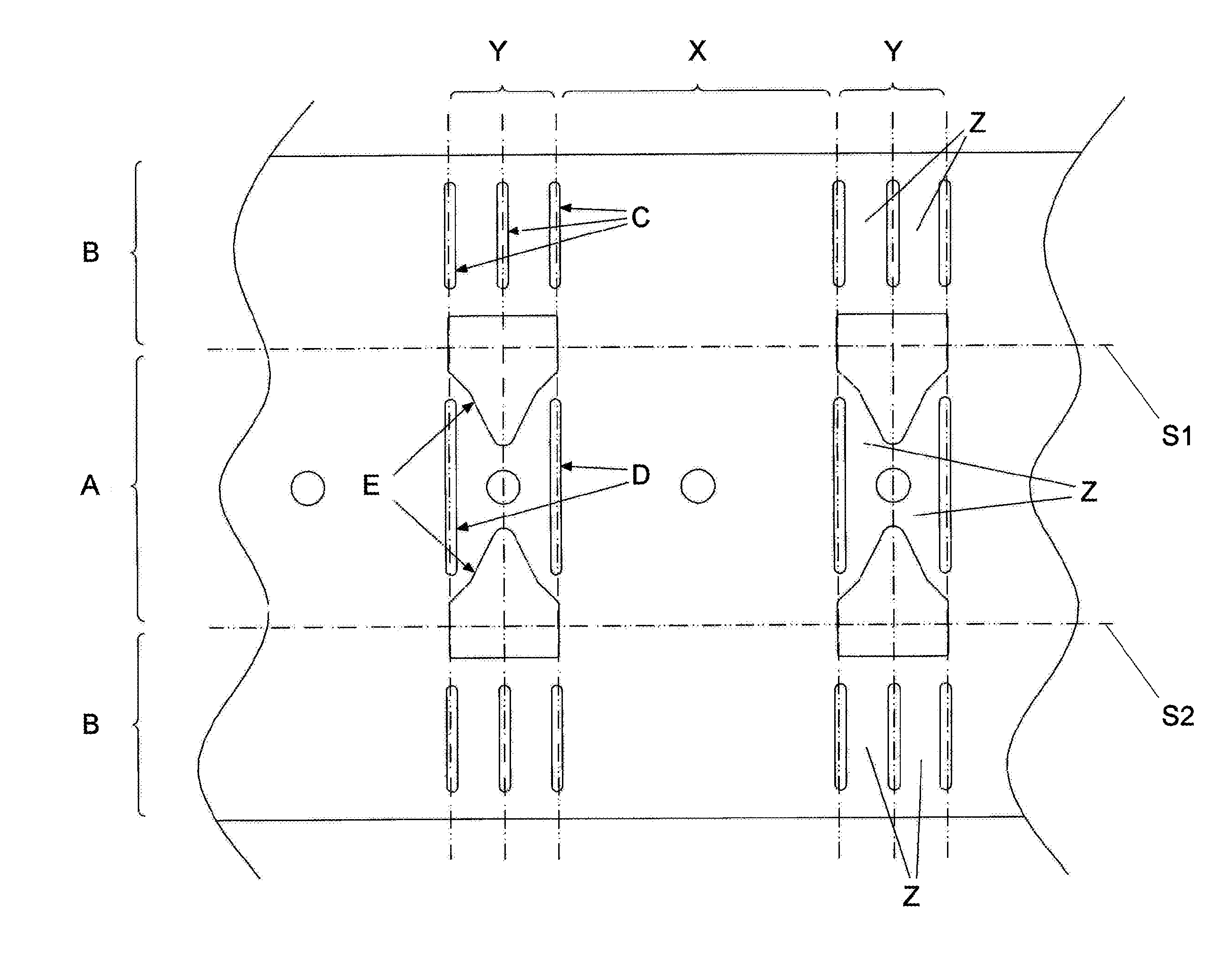
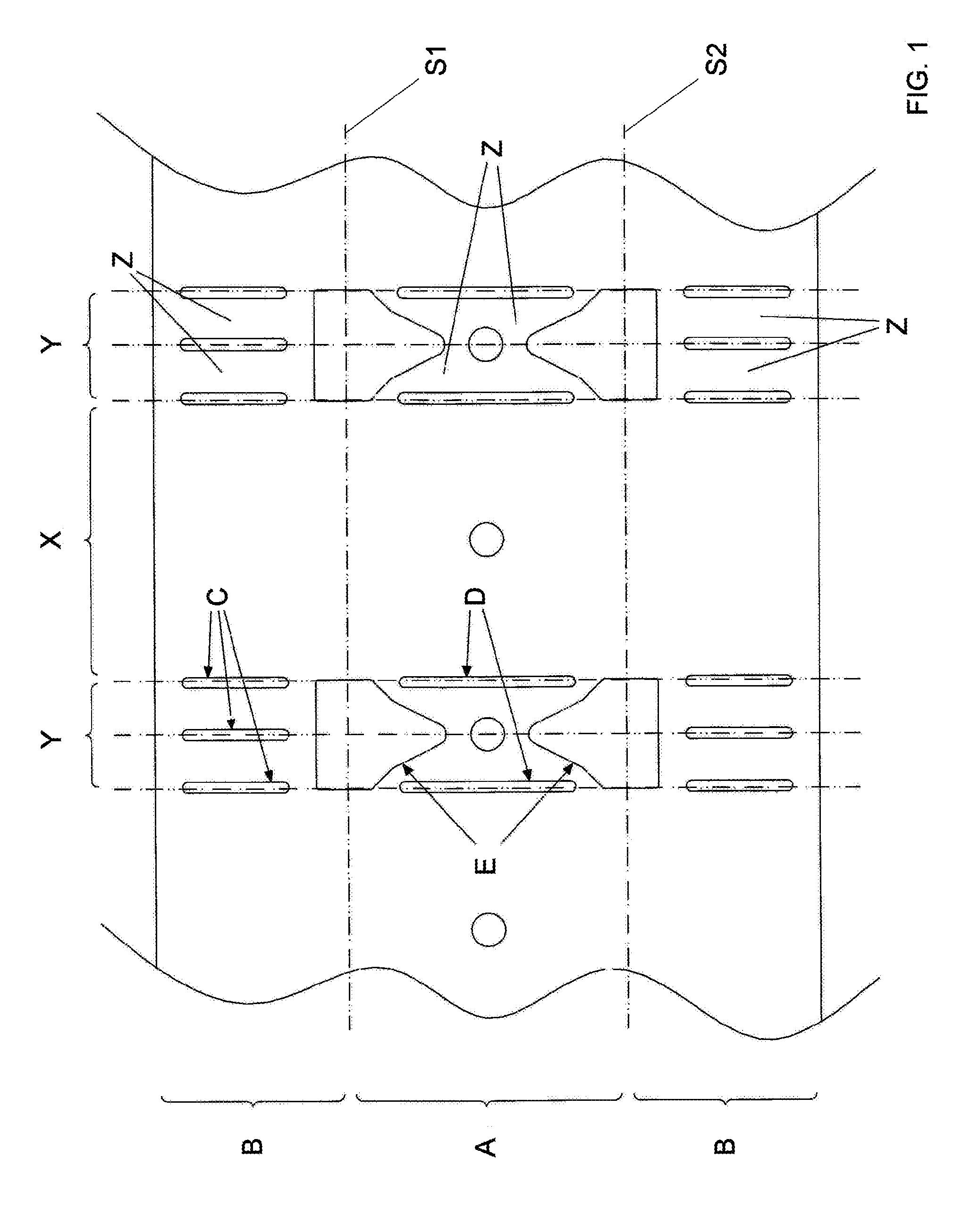
[0030]A metal strip according to the invention is provided with areas (X) without gaps alternating to areas (Y) with cuts and die cuts.

[0031]The folding lines (S1, S2) are indicated by dash-point lines.

[0032]The plate strip comprises a center band (A) and two side bands or edges (B).

[0033]Each side band (B), with respect to the area (Y) with cuts, is provided with three cuts (C) that are parallel to one another and perpendicular to the edge of the plate strip.

[0034]Each center band (A), with respect to the area (Y) with cuts, is provided with two cuts (D) that are parallel to each other and aligned with the external cuts (C) present on the side bands (B).

[0035]There are two holes (E) with five sides, of which three sides are orthogonal to one another and arranged in the area included between the side bands (B) and the centre band (A), and two sides are inclined with respect to each other and to the other sides with the vertex included between them facing towards the centre of the ce...


PUM


Abstract

A deformable guide for partitions in general includes a plate strip that is die cut, cut and bent to form a U and that has continuous sections alternating with sections provided with cuts and holes. Each section with cuts and holes is provided at least with cuts and holes that are orthogonal to the edge of the plate strip and suited to divide such section into portions, wherein those portions are bent with respect to each other to form a 115° angle.

Description

FIELD OF THE INVENTION[0001]The present patent concerns the field of wall construction with prefabricated panels applied to a light bearing structure, and in particular it concerns a new type of section bar for making light bearing structures on which prefabricated panels can be applied and fixed.BACKGROUND OF THE INVENTION[0002]At present metallic structures supporting panels in plasterboard or other similar materials are widely used for making partitions or furnishing walls. Said structures are easy and quick to make and allow walls to be obtained that have special or arched shapes that are otherwise expensive and difficult to obtain with bricks and cement.[0003]Rectilinear walls or partitions can be made with plasterboard panels applied to a frame of rectilinear elements in wood or metal section bars.[0004]If the walls are not rectilinear, deformable guides are used that are constituted by a die cut and bent plate so as to form a continuous assembly of modular box-shaped elements...

Claims


Application Information

Patent Timeline
Patent Type & Authority Applications(United States)
IPC IPC(8): E04C3/00E05D15/06
CPCE04C3/00E05D15/0652E04B2/7457E04B9/061E04B9/065E04B2002/7481E04C2003/0421E04C2003/0434E04C2003/0473E04B2/74
Inventor CECCATO, NICOLA
Owner CECCATO NICOLA
Why Eureka
Try Eureka