Double layered exhaust gas purification catalyst

a purification catalyst and exhaust gas technology, applied in physical/chemical process catalysts, metal/metal-oxide/metal-hydroxide catalysts, separation processes, etc., can solve the problems of sintering, particle growth, and inability to maintain high purification performance with just a three-way catalyst, and achieve high exhaust gas purification performance and satisfying catalyst warm-up performance

Active Publication Date: 2013-11-21
TOYOTA JIDOSHA KK
View PDF4 Cites 43 Cited by
  • Summary
  • Abstract
  • Description
  • Claims
  • Application Information

AI Technical Summary

Benefits of technology

The exhaust gas purification catalyst described in this patent has two main benefits: it prevents particles from growing in certain parts of the system and promotes better engine cold start-up performance. By adding a specific type of material called oxygen storage material (OSM) to the front-stage lower catalyst layer, the catalyst reduces particulate matter formation in the rear-stage lower and upper catalyst layers. Additionally, placing the OSM in this location improves the flow of hydrocarbons (HCs) through the entire system, leading to more efficient cleaning at the front-stage lower catalyst layer. Overall, this design results in higher levels of exhaust gas purification across the entire catalyst system.

Problems solved by technology

The technical problem addressed in this patent text relates to finding ways to prevent degradation of exhaust gas purification performance caused by sintering-related particle growth of the noble metals used in three-way catalysts, particularly at high temperatures encountered in real-world driving conditions. This issue needs to be solved to ensure continued effectiveness of exhaust gas purification catalysts in meeting stricter global emissions standards.

Method used


Image

  • Double layered exhaust gas purification catalyst
  • Double layered exhaust gas purification catalyst
  • Double layered exhaust gas purification catalyst

Examples


example 1

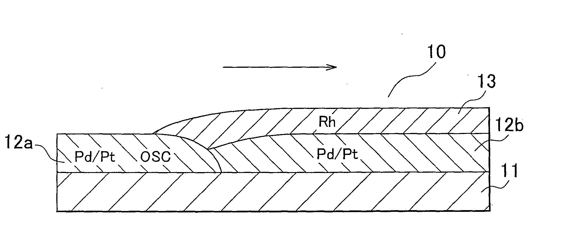
[0062][Formation of the Front-Stage Lower Catalyst Layer]

[0063]Using a palladium nitrate solution, Pd (1.0 g / substrate-L (per 1 L of substrate)) was supported by impregnation on 35 g / substrate-L of a ZrO2 composite oxide powder (ZrO2: 68 wt %, La2O3: 7 wt %, Y2O3: 25 wt %). This Pd-loaded ZrO2 composite oxide powder was then mixed with 77 g / substrate-L La-doped Al2O3 (Al2O3: 96 wt %, La2O3: 4 wt %), 35 g / substrate-L tetragonal CeO2—ZrO2 composite oxide (CeO2 / ZrO2=1.43 (molar ratio)) as an Oxygen storage material, and 5 g / substrate-L Al2O3 binder, and a coating slurry was prepared by the addition of water. The obtained slurry was then coated by a washcoat method on the exhaust gas upstream portion of a ceramic honeycomb substrate (φ103 mm, L105 mm, volume 875 cc) having a large number of wall-partitioned cells; coating was performed over a distance of 35% with respect to the total length of the honeycomb substrate. This was followed by drying and firing to form the front-stage lower ...

example 2

[0073]An exhaust gas purification catalyst B was obtained proceeding as in Example 1, but using a tetragonal CeO2—ZrO2 composite oxide with CeO2 / ZrO2=0.35 (molar ratio) as the oxygen storage material in the front-stage lower catalyst layer.

example 3

[0074]An exhaust gas purification catalyst C was obtained proceeding as in Example 1, but using a tetragonal CeO—ZrO2 composite oxide with CeO2 / ZrO2=0.49 (molar ratio) as the oxygen storage material in the front-stage lower catalyst layer.


PUM

PropertyMeasurementUnit
Fractionaaaaaaaaaa
Fractionaaaaaaaaaa
Fractionaaaaaaaaaa

Abstract

Provided is an exhaust gas purification catalyst (10) that has a substrate (11), a lower catalyst layer (12) that is formed on the substrate and contains at least one of Pd and Pt, and an upper catalyst layer (13) that is formed on the lower catalyst layer and contains Rh. A region that does not contain the upper catalyst layer is disposed on the exhaust gas upstream side of this exhaust gas purification catalyst, and the lower catalyst layer is formed of a front-stage lower catalyst layer (12a) on the exhaust gas upstream side and a rear-stage lower catalyst layer (12b) on the exhaust gas downstream side. The Front-stage lower, catalyst layer contains an oxygen storage material.

Description


Claims


Application Information

Patent Timeline
Owner TOYOTA JIDOSHA KK
Why Eureka
Try Eureka