System and method for purifying an exhaust gas

a technology of system and method, applied in the direction of machines/engines, separation processes, mechanical equipment, etc., can solve the problems of affecting the purification effect of exhaust gas

Inactive Publication Date: 2005-10-06
HONDA MOTOR CO LTD
View PDF8 Cites 10 Cited by
  • Summary
  • Abstract
  • Description
  • Claims
  • Application Information

AI Technical Summary

Benefits of technology

[0026] The system described above is able to add the reductant without its wasteful consumption.
[0027] When the unit for adding reductant is so arranged that it is able to add the reductant upstream the second plasma unit and HC is selected for the reductant, second energetic p

Problems solved by technology

However, there has been a problem that use of DPF made of a porous filter, which causes poor flow of an exhaust gas due to greater resistance (pressure loss), does not allow efficient utilization of engine power.
DPF has another problem that its reactivation requires controlling of an engine described above and its temperature possibly exceeds 1000 degrees Celsius during reactivation, which results in damage of DPF such as melting and breaking.
The first method described above has posed a problem that there is not sufficient unburned HC in an exhaust gas.
The second m

Method used


Image

  • System and method for purifying an exhaust gas
  • System and method for purifying an exhaust gas
  • System and method for purifying an exhaust gas

Examples


example 1

(3-1) Example 1

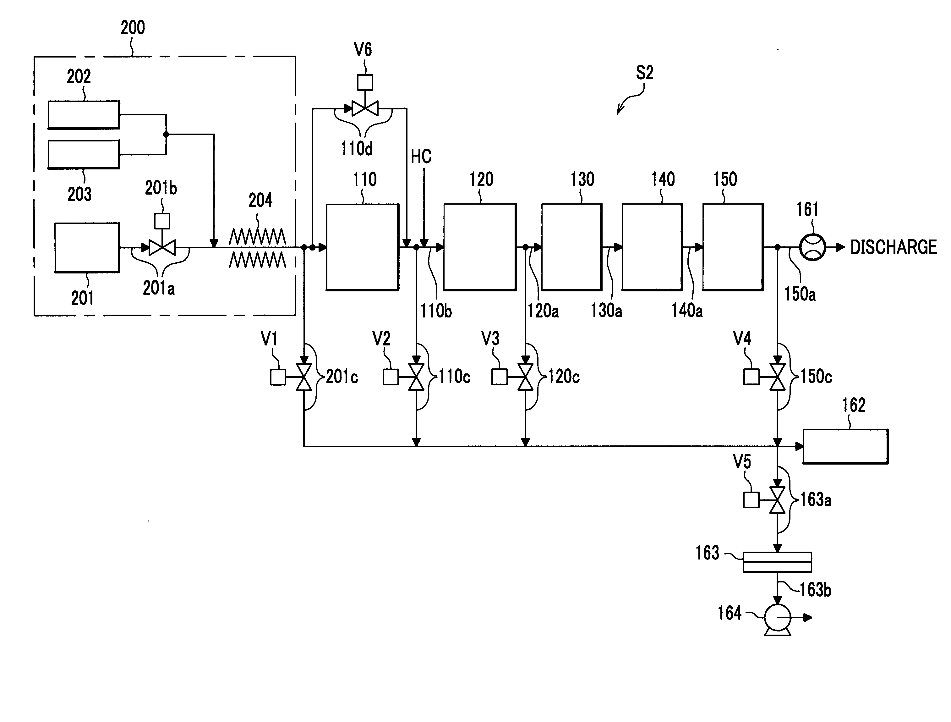
[0118] Taking into account the power density of plasma space described above, 6.0 and 2.2 (W / cm3) were selected for the first and second plasma units 110 and 120, respectively, in an example 1. In setting these values, sinusoidal alternating current of 600 Hz was imposed on the first plasma unit 110 at AC voltage of 6.6 kVpp and resulting current of 15 mArms was observed. For the second plasma unit 120, AC current of 800 Hz was imposed at 9.2 kVpp and current of 5.3 mArms was observed.

[0119] An exhaust gas, which was discharged from a diesel engine whose characteristics are shown in FIG. 7, was brought into the system S2 for purifying an exhaust gas. Measurement was conducted for acquiring data to be used for calculation of rates for purification of PM and NOx based on expressions (1) and (3), while opening and closing of the valves V1, V4 and V5 were selectively controlled. γ=m5-m6m5×100(3)

where γ represents a rate for purification of NOx in the form of percentage...

example 2

(3-2) Example 2

[0121] Power densities of plasma space of 8.0 and 2.2 (W / cm3) were selected for the first and second plasma units 110 and 120, respectively, in an example 2. In setting these values, sinusoidal alternating current of 3000 Hz was imposed on the first plasma unit 110 at AC voltage of 7.0 kVpp and resulting current of 30 mArms was observed. The same conditions as those of the example 1 were selected for the second plasma unit 120.

[0122] Measurement was conducted for rates for purification of PM and NOx in the same manner as those of the example 1. Results of measurement are shown in FIG. 6.

example 3

(3-3) Example 3

[0123] An example 3 provides a case to be compared with the examples 1 and 2, where the first and second plasma units 110 and 120 were not brought to operation and addition of HC was not carried out in the system S2 for purifying an exhaust gas. Results of measurement are shown in FIG. 6.

[0124] Conditions of the first and second plasma unit 110 and 120 for the examples 1, 2 and 3 are summarized in FIG. 9.

(4) Results

[0125] As obviously seen from FIG. 6, the examples 1 and 2 are able to provide better purification of an exhaust gas, which achieves rates for purification of PM and NOx not less than 80%. In contrast, the example 3 shows inferior results, a remarkably low rate of 30% for purification of PM and a rate of 60% for purification of NOx.


PUM


Abstract

A system for purifying an exhaust gas includes a plasma unit and a catalyst unit. The plasma unit generates energetic plasma species which react with particulate matters and nitrogen oxides contained in the exhaust gas. The catalyst unit has a catalyst which reacts with the exhaust gas. The plasma unit is disposed upstream relative to the catalyst unit in a direction of flow of the exhaust gas and the system provides sequential purification for the particulate matters and the nitrogen oxides.

Description

BACKGROUND OF THE INVENTION [0001] The present invention relates to a system and method which are able to purify particulate matters (hereinafter referred to as PM) and nitrogen oxides (hereinafter referred to as NOx) contained in an exhaust gas discharged from an internal combustion engine, such as a diesel engine mounted on an automobile, by means of plasma and a catalyst. [0002] An exhaust gas, which is discharged from an internal combustion engine such as a diesel engine or lean burn engine mounted on an automobile, contains particulate matters (PM). It is known that a diesel particulate filter (hereinafter referred to as DPF) is installed downstream an internal combustion engine so as to reduce PM. A DPF, which generally includes a porous filter made of ceramics, decreases PM so as to purify an exhaust gas. This is carried out by making the exhaust gas pass through the DPF so as to separate and collect PM. [0003] When the DPF captures a certain amount of PM, its reactivation is...

Claims


Application Information

Patent Timeline
IPC IPC(8): F01N3/02B01D53/56B01D53/74B01D53/94F01N3/01F01N3/08F01N3/20F01N3/24F01N3/28F01N3/36F01N13/02
CPCF01N3/0814F01N3/0842F01N3/0892F01N3/106F01N13/009F01N2240/28F01N2390/00F01N2610/03Y02T10/24F01N3/2828Y02T10/12
Inventor NAKANISHI, YOSHIYUKIDOSAKA, KENJIMIKI, MASANOBUIWAMA, KEIZOTERADA, KAZUHIDE
Owner HONDA MOTOR CO LTD
Why Eureka
Try Eureka