Tool hanger

a technology for tools and hangers, which is applied in the field of display devices or hangers, can solve the problems of malice not being able to remove the socket from the engagement portion, and the hangers mentioned above being unsuitable for sockets or tools, and achieves the effects of reliable fixing, anti-detachment function, and engaging

Inactive Publication Date: 2013-11-28
LIN MING HUNG
View PDF9 Cites 8 Cited by
  • Summary
  • Abstract
  • Description
  • Claims
  • Application Information

AI Technical Summary

Benefits of technology

[0007]The main object of the present invention is to provide a burglarproof t...

Problems solved by technology

As such, the malice can not remove the socket from the engagement portion.
However, th...

Method used


Image

  • Tool hanger
  • Tool hanger
  • Tool hanger

Examples


Embodiment Construction

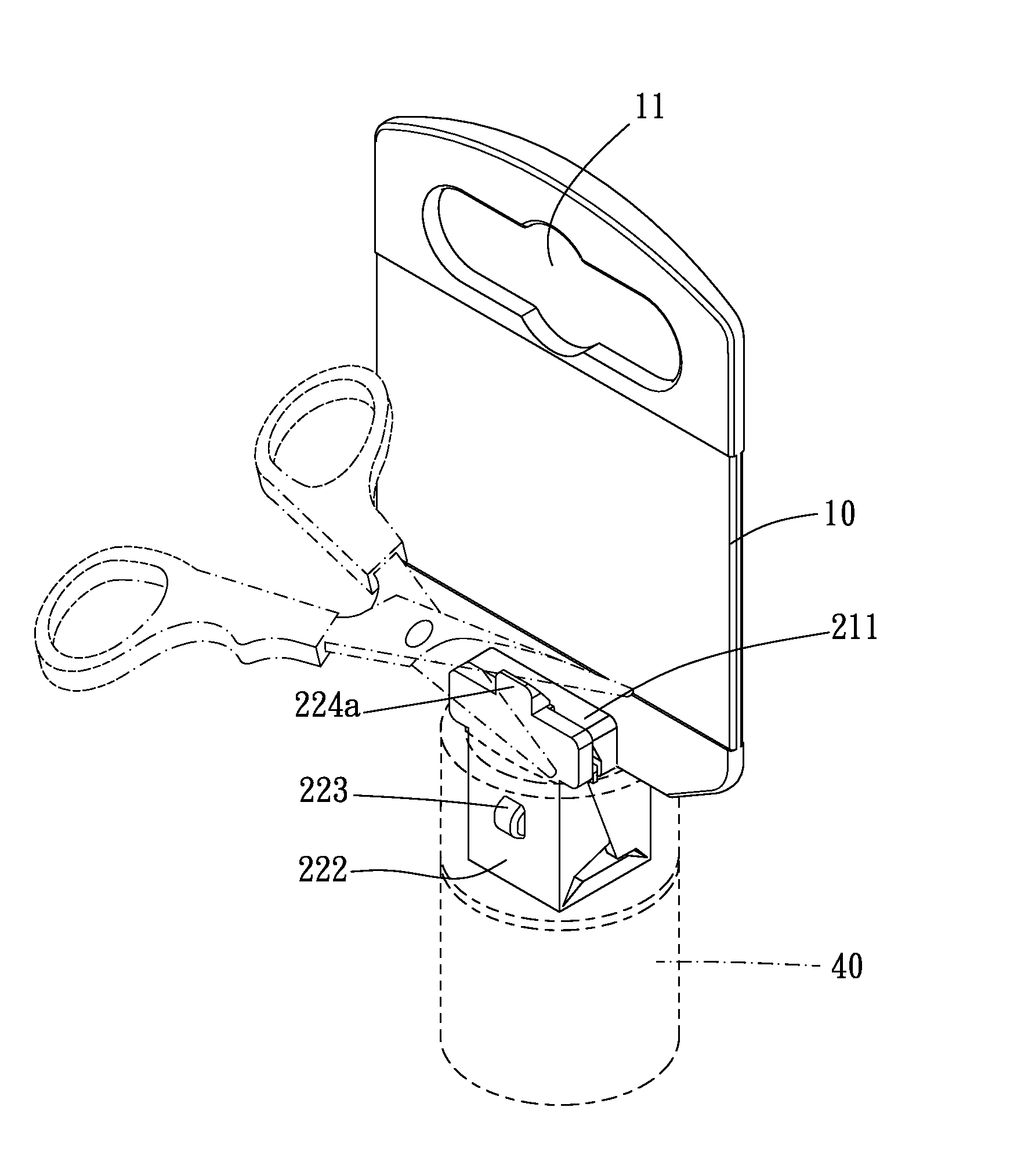
[0021]Please refer to FIG. 1 to FIG. 3 for a first embodiment of the present invention. The tool hanger of the present embodiment includes a hanging member 10 and a tool holding member 20.

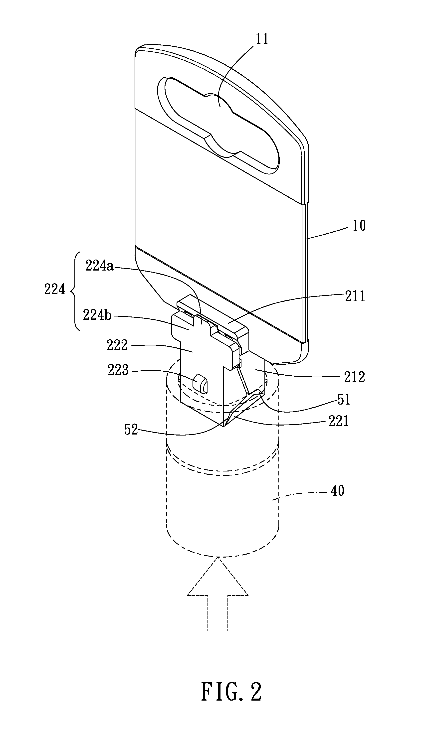
[0022]The hanging member 10 is formed with a hanging hole 11 which is adapted for a hook or a pole to pierce therethrough. Thus, the hanging member 10 can be hung on wall or a shelf.

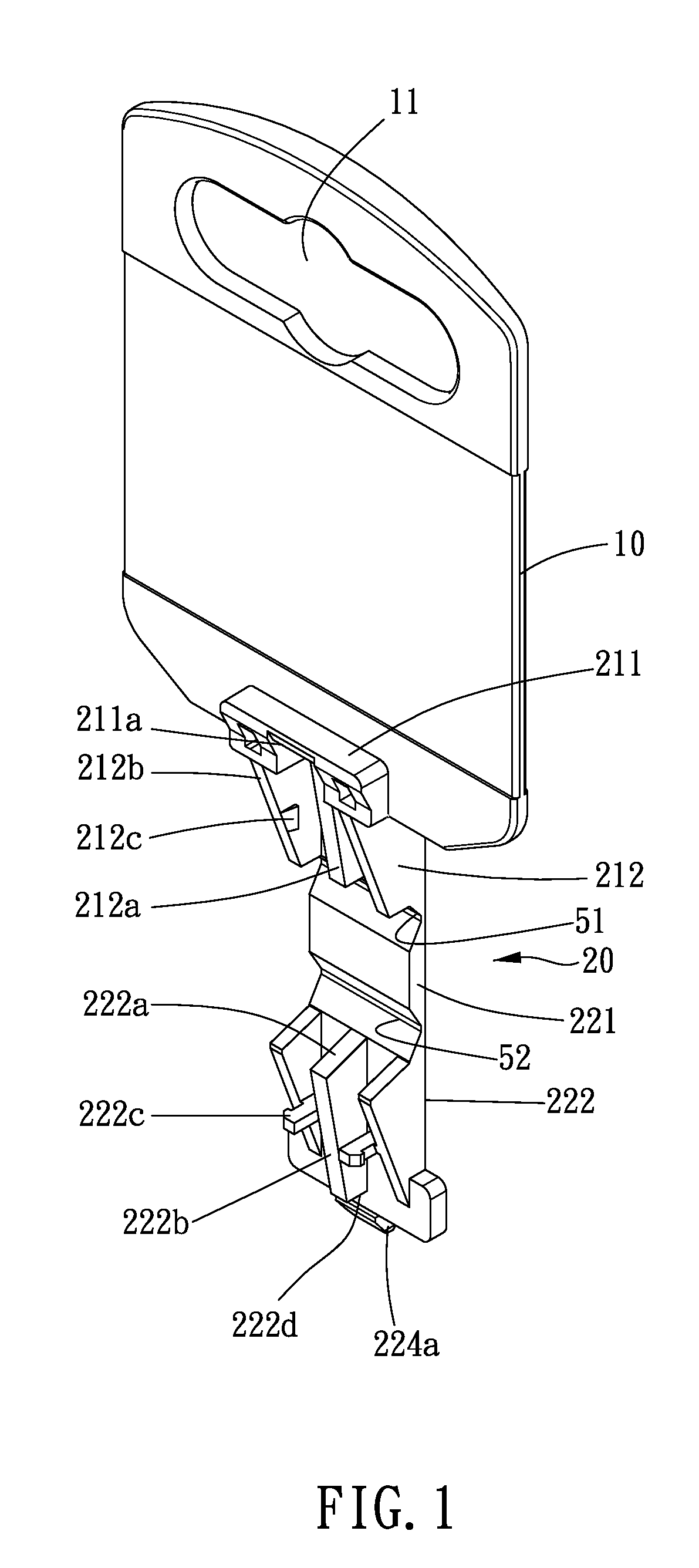
[0023]The tool holding member 20 includes a fixation mechanism and a burglarproof mechanism. The fixation mechanism is disposed to the hanging member. One end of the burglarproof mechanism is pivotably disposed to the fixation mechanism.

[0024]The fixation mechanism includes a fixation portion 211 and a guiding portion 212. The fixation portion 211 protrudes from a foreside of the hanging member 10, preferably from a bottom edge of the hanging member 10. The guiding portion 212 stretches downwardly from one end of the fixation portion 211. The fixation portion 211 includes a slant surface 211a. The guiding portion 212 in...


PUM


Abstract

A tool hanger includes a hanging member and a tool holding member. The tool holding member can be folded up and fitted in a connection hold of a tool, such as a socket. The tool is then engaged by the tool holding member. The distal end of the tool holding member undetachably clips on the other end of the tool holding member. Thus, the unauthorized removal of the tool is prohibited, and burglarproof function is achieved.

Description

BACKGROUND OF THE INVENTION[0001]1. Field of the Invention[0002]The present invention relates to a displaying device or a hanger for displaying socket, connector, or linkage on a shelf.[0003]2. Description of the Prior Art[0004]Conventional hangers for displaying socket or connector are usually provided with locking functions. Therefore, unauthorized removal of the merchandise is prohibited to fight against the malice. For example, socket hanger which includes a hanging plate, a hanging piece, and an elastic slice. The hanging piece has an engagement portion at a lower portion thereof. The engagement portion is inserted in a connection hole of a socket, so that the socket is removably attached to the engagement portion. An engagement slice is then inserted into a through hole of the socket, engaging the engagement portion with a hook portion disposed at a top end of the engagement slice. A bottom edge of the engagement slice abuts against a step portion of the socket between the con...

Claims


Application Information

Patent Timeline
IPC IPC(8): F16M13/02
CPCF16M13/02B25H1/00A47F5/0006A47F5/0861
Inventor LIN, MING-HUNG
Owner LIN MING HUNG
Why Eureka
Try Eureka