Laser marker
- Summary
- Abstract
- Description
- Claims
- Application Information
AI Technical Summary
Benefits of technology
Problems solved by technology
Method used
Image

Examples
Example
First Embodiment
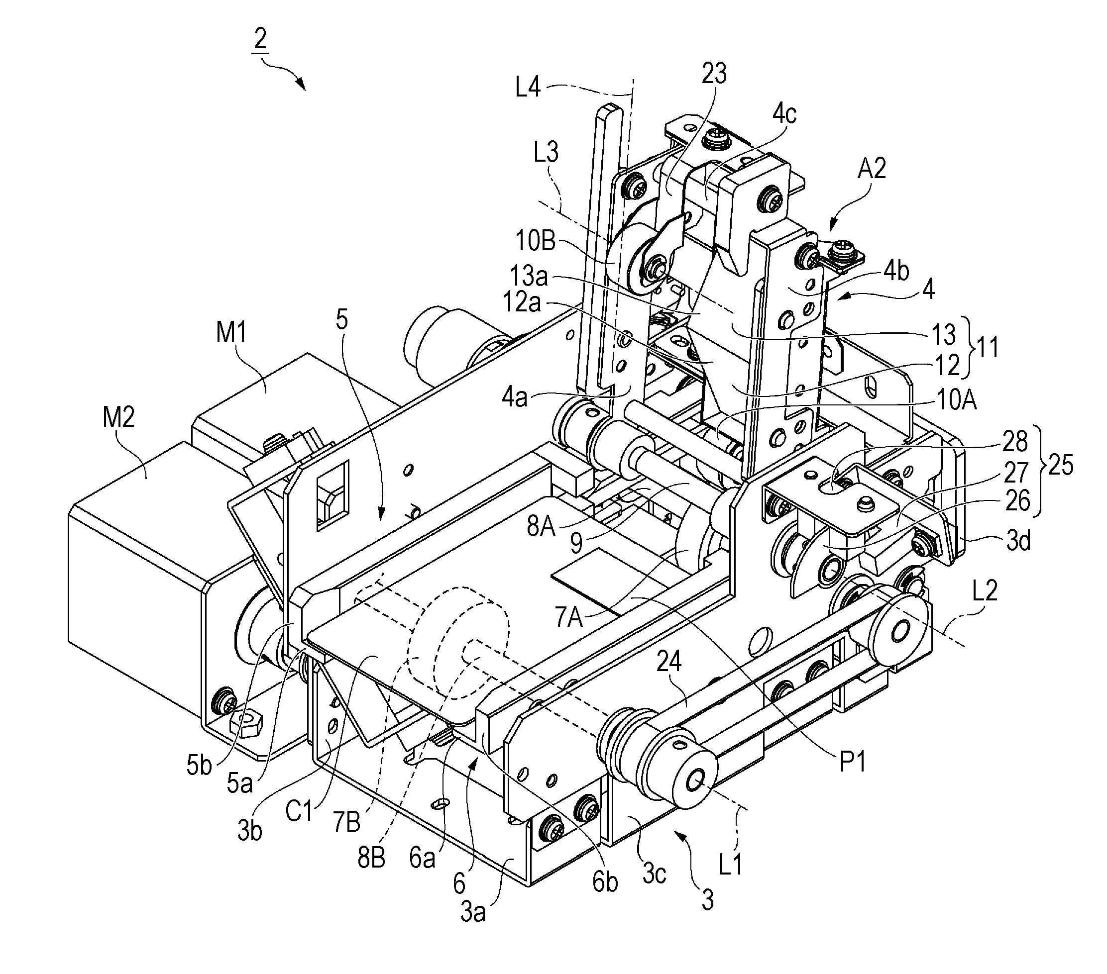
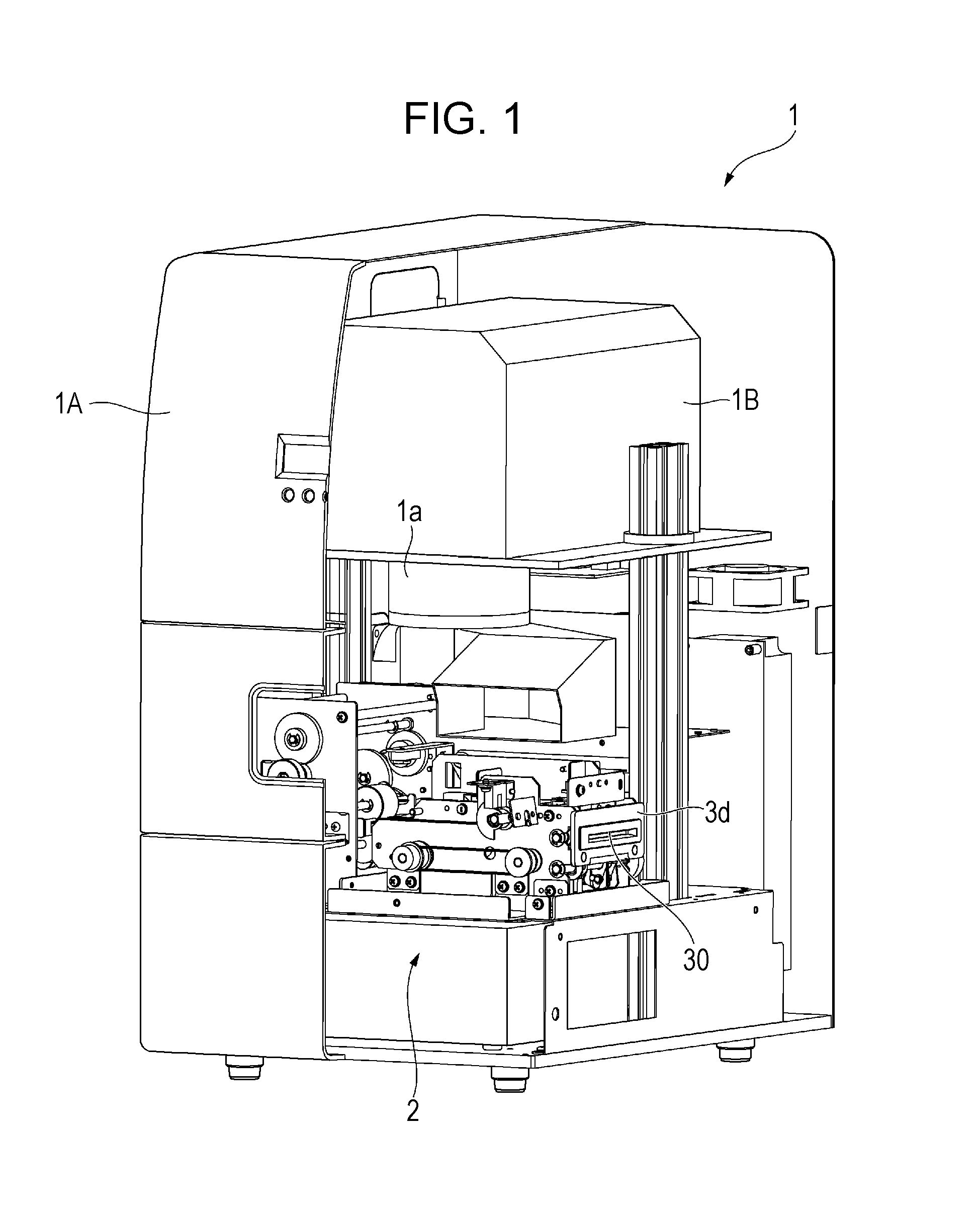
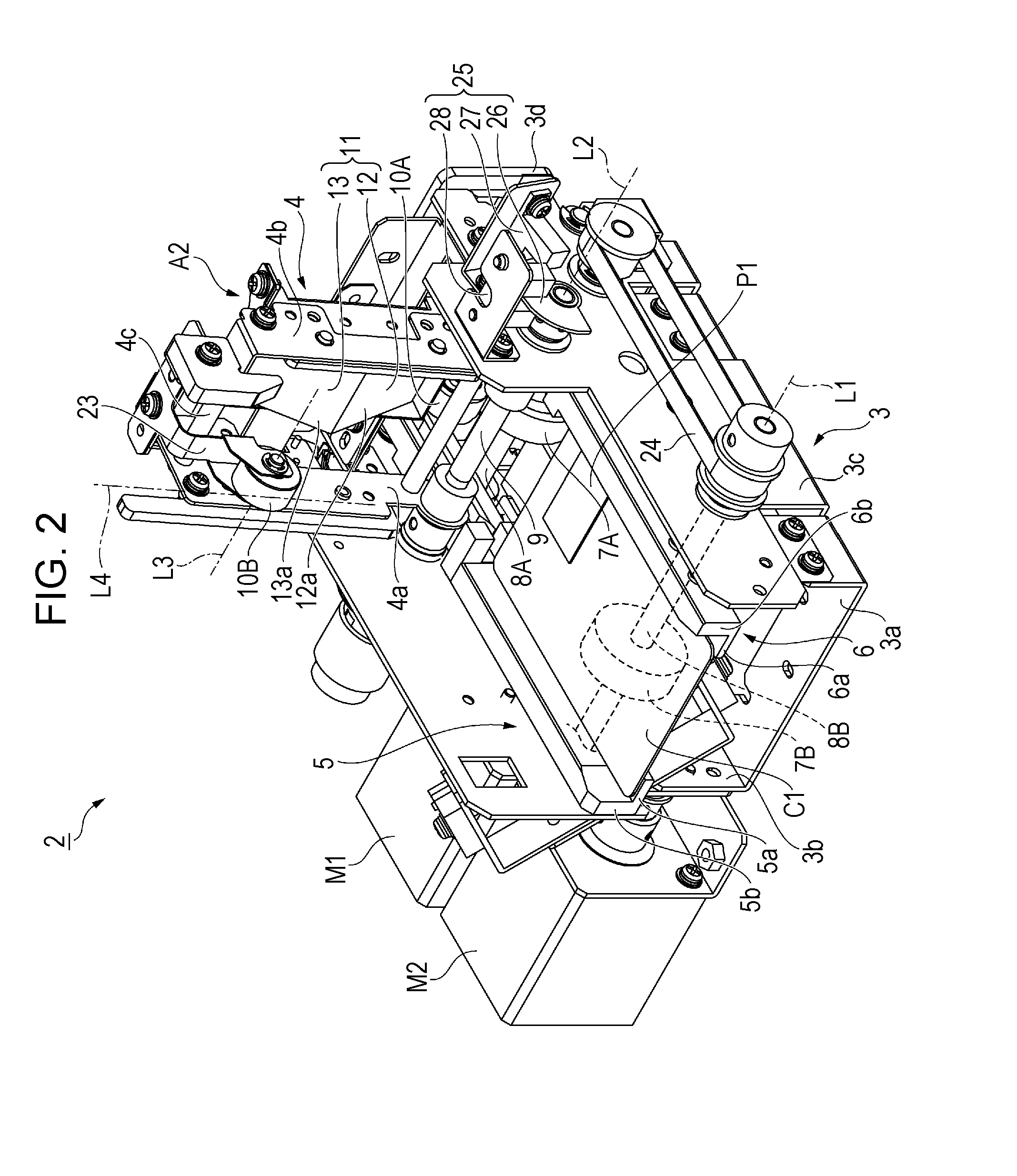
[0042]FIGS. 1 to 6 illustrate a laser marker 1 for printing a lenticular image and an ordinary image on a card C1, which is an example of a sheet. The lenticular image is formed in a lenticular portion P1 of the card C1. The lenticular portion P1 is a portion of the card C1 on which a lenticular lens is formed. The lenticular lens is transparent and has a sheet-like shape. The lenticular image is formed under the lenticular lens. The laser marker 1 includes a laser irradiation device 1B and a housing 1A. The laser irradiation device 1B emits a laser beam from a head 1a, which faces downward. The housing 1A is disposed in an upper part of the laser marker 1 and houses the laser irradiation device 1B. The laser irradiation device 1B can freely move a point that is irradiated with a laser beam in the horizontal direction by moving a scan mirror. A transport device 2 is disposed below the laser irradiation device 1B in the housing 1A. The transport device 2 transports th...
Example
Second Embodiment
[0063]As illustrated in FIGS. 7 to 11, a laser marker according to the second embodiment includes a transport device 2A, instead of the transport device 2 of the laser marker 1. The transport device 2A includes a prism 14, instead of the prism 11 of the transport device 2. The prism 14 is different from the prism 11. The laser marker prints a lenticular image whose appearance changes when a card C2 is tilted around an axis L8 that diagonally intersects the transport direction L4.
[0064]As illustrated in FIGS. 7 to 9, the prism 14 includes a first right-angle prism 15 (first prism portion) and a second right-angle prism 16 (second prism portion), which are arranged side by side along the transport direction L4, in which the pinch roller 10B transports the card C2. In plan view, the right-angle prisms 15 and 16 are disposed along the axis L10, which diagonally intersects the transport direction L4. To be specific, the first right-angle prism 15 is disposed on the back ...
Example
Third Embodiment
[0068]As illustrated in FIGS. 12 to 17, a laser marker according to the third embodiment includes a transport device 2B, instead of the transport device 2 of the laser marker 1. The transport device 2B includes a second rotation member 17 in addition to the first rotation member 4, which is the same as the rotation member 4 of the transport device 2. The laser marker prints, in addition to a lenticular image whose appearance changes as the card C3 is tilted around the axis L7, which is perpendicular to the transport direction L4, a lenticular image whose appearance changes as the card C3 is tilted around an axis L9 that is parallel to a transport direction L6. The rotation member 17 rotates between a holding position A3 and a withdrawn position A4. In the holding position A3, the rotation member 4 holds the card C3 in cooperation with the base unit 3. In the withdrawn position A4, the rotation member 4 is located outside of the optical path of a laser beam. The rotat...
PUM
 Abstract
Description
Claims
Application Information
 - R&D Engineer
- R&D Manager
- IP Professional
- Industry Leading Data Capabilities
- Powerful AI technology
- Patent DNA Extraction
Browse by: Latest US Patents, China's latest patents, Technical Efficacy Thesaurus, Application Domain, Technology Topic.
© 2024 PatSnap. All rights reserved.Legal|Privacy policy|Modern Slavery Act Transparency Statement|Sitemap