
Sheet processing apparatus and image forming apparatus

a technology of image forming apparatus and sheet processing apparatus, which is applied in the directions of packaging, transportation and packaging, paper/cardboard containers, etc., can solve the problems of unfavorable booklet press mark, difficult stacking of many booklets, and increasing bends of the fold end portion from the inside of the booklet to the outside (cover), and achieve the effect of stably forming the fold

Inactive Publication Date: 2013-10-01
CANON KK
View PDF7 Cites 1 Cited by
  • Summary
  • Abstract
  • Description
  • Claims
  • Application Information

AI Technical Summary

Benefits of technology

The invention is a sheet processing apparatus that moves the pressing portion or sheet holding portion to the fold end portion of a sheet bundle to prevent bending and form a stable fold. This ensures that the fold is not only aesthetically pleasing, but also functionally sound.

Problems solved by technology

When a sheet bundle contains many sheets (e.g., 20 sheets or more), however, the fold end portion increasingly bends from the inside of the booklet to the outside (cover) and may not be folded fully.
It is difficult to stack many booklets.
Such a press mark is undesirable on booklets for a cosmetic reason.
However, nipping to fasten the booklet presses the booklet in a thickness direction and bulges the fold end portion.
As a result, the pressing roller may deform unintended sheets (e.g., those at the center) of the booklet and degrade the aesthetic quality at the fold end portion.
However, the fold end portion may not be fully pressed if a small amount of the fold end portion is deformed.
As a result, fold end portions are inconsistently shaped and the fold end portion quality may degrade.

Method used


Image

  • Sheet processing apparatus and image forming apparatus
  • Sheet processing apparatus and image forming apparatus
  • Sheet processing apparatus and image forming apparatus

Examples


first modification

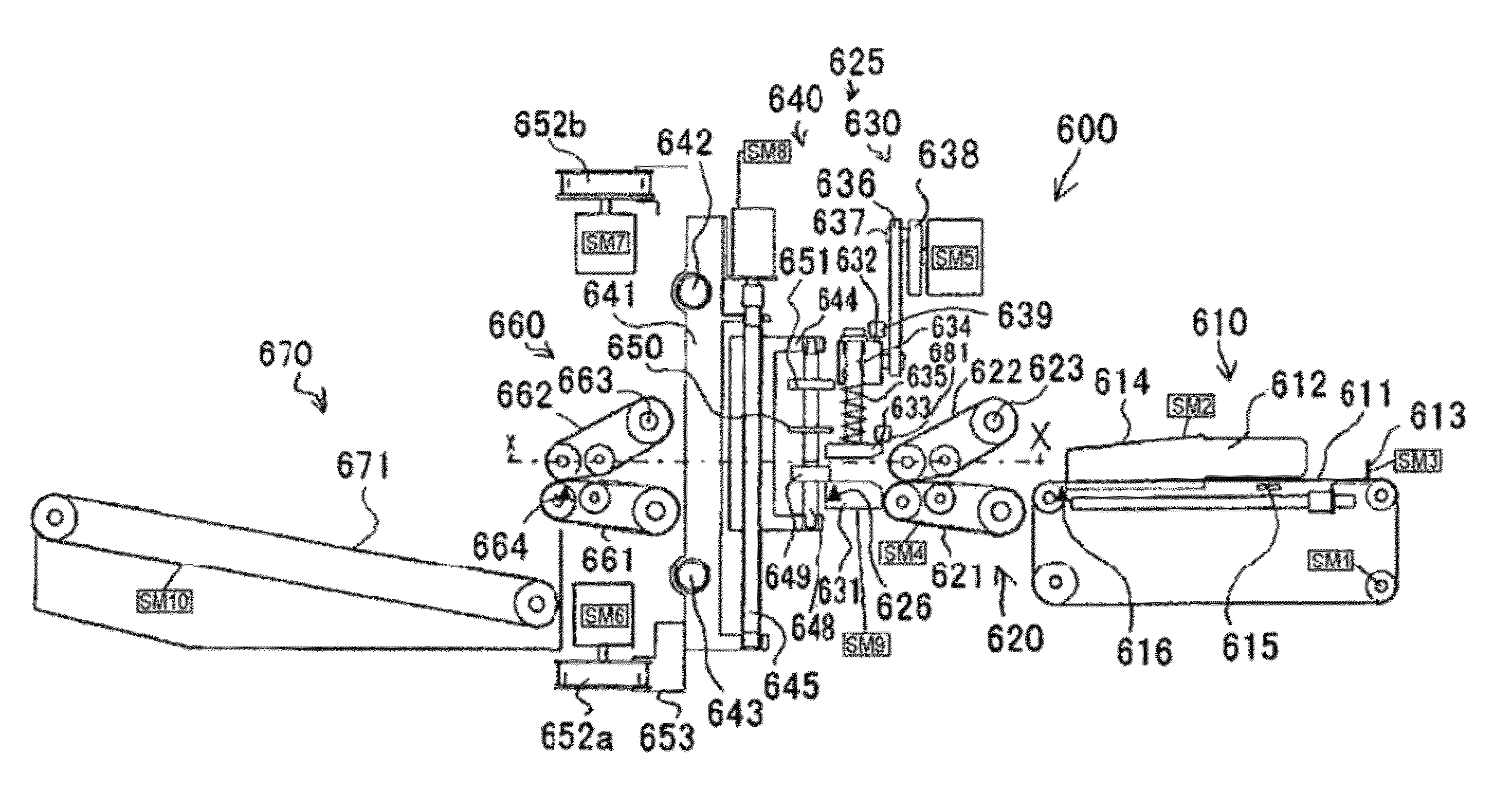
[0122]The tip positioning process in the deforming process enabling mode according to the first modification differs from the embodiment in that the pressing unit moving motor SM9 drives while the upper pressing plate 633 and the lower pressing plate 631 hold a booklet. The first modification describes only differences from the embodiment and will not be repeated. A description about the same contents as the embodiment. The same effect as the embodiment is ensured for a configuration that is common to the first modification and the embodiment.

[0123]As illustrated in FIG. 18, the tip positioning process starts and places the booklet against the positioning rollers 649a and 649b to complete the positioning (step ST201). The inlet conveying portion 620 then stops driving (step ST202). At this time, the tip positioning process using the positioning rollers 649a and 649b has positioned the booklet so that the fold end portion thereof is located between the upper pressing plate 633 and th...

second modification

[0128]The tip positioning process in the deforming process enabling mode according to a second modification differs from the embodiment in that the booklet thickness determines the amount of projection (tip position). The second modification describes only differences from the embodiment and will not be repeated a description about the same contents as the embodiment. The same effect as the embodiment is ensured for a configuration that is common to the second modification and the embodiment.

[0129]As illustrated in FIG. 19, the tip positioning process starts and places the booklet against the positioning rollers 649a and 649b to complete the positioning (step ST301). The inlet conveying portion 620 then stops driving (step ST302). At this time, the tip positioning process using the positioning rollers 649a and 649b has positioned the booklet so that the fold end portion thereof is located between the upper pressing plate 633 and the lower pressing plate 631 as illustrated in FIG. 13...


PUM

PropertyMeasurementUnit
distanceaaaaaaaaaa
thicknessaaaaaaaaaa
bendingaaaaaaaaaa

Abstract

A finisher deforms a fold end portion of a sheet bundle with a lower pressing plate and an upper pressing plate. A pressing unit holds a sheet bundle so that the fold end portion is positioned between the lower pressing plate and the upper pressing plate. A third pressing roller includes a third pressing surface that presses the fold end portion of the sheet bundle between the lower pressing plate and the upper pressing plate. The third pressing roller moves in between the lower pressing plate and the upper pressing plate. The third pressing roller or the pressing unit moves so that the third pressing surface of the third pressing roller presses the fold end portion at a predetermined position based on a tip of the fold end portion. The fold end portion projects after the sheet bundle is held between the lower pressing plate and the upper pressing plate.

Description

BACKGROUND OF THE INVENTION[0001]1. Field of the Invention[0002]The present invention relates to a sheet processing apparatus and an image forming apparatus and more particularly to a sheet processing apparatus and an image forming apparatus having the same, wherein the sheet processing apparatus folds a sheet bundle in two and deforms a fold end portion of the folded sheet bundle.[0003]2. Description of the Related Art[0004]A conventionally known sheet processing apparatus bundles multiple sheets having images formed thereon, staples the center of the sheets, folds the sheets, and shapes them into a booklet-shaped sheet bundle (hereafter also referred to as a booklet). The sheet processing apparatus overlays sheets having images formed thereon one by one to prepare a sheet bundle. The sheet processing apparatus then staples the center of the sheet bundle and then folds the sheet bundle by pressing the sheet bundle into a nip of folding rollers using a pressing plate.[0005]When a sh...

Claims


Application Information

Patent Timeline
Patent Type & Authority Patents(United States)
IPC IPC(8): B31F1/00
CPCB65H45/18B65H2301/51232B65H2511/20B65H2511/222B65H2701/13212B65H2801/27B65H2220/02B65H2220/11B65H2220/01
Inventor SATO, TOMOHARUFUKATSU, YASUOKATO, HITOSHIISHIKAWA, NAOKI
Owner CANON KK
Learn More