Image forming apparatus and image forming method

Inactive Publication Date: 2011-06-02
SEIKO EPSON CORP
View PDF4 Cites 0 Cited by
  • Summary
  • Abstract
  • Description
  • Claims
  • Application Information

AI Technical Summary

Benefits of technology

[0011]Therefore, even after the leading end of the transfer medium reaches the position where the transfer medium transport section starts to suck the transfer medium, while the transfer medium is moved by the driving force at the transfer nip portion, the back surface of the transfer medium comes into contact with a plurality of contact members of the transfer medium transport section, so that the friction between the transfer medium and the transfer medium transport section is reduced. In particular, if the contact member is a roller member which rotates about a shaft extending in the direction perpendicular or approximately perpendicular to the transfer medium movement direction, as the back surface of the transfer medium is guided by the roller member, the friction between the transfer medium and the transfer medium transport section is more effectively reduced. As a result of this, it becomes possible to suppress changes in the position of the transfer medium and instability of the transfer medium according to the changes. In particular, since the friction between the transfer medium and the transfer medium transport section is reduced, so that changes in position of the transfer medium is suppressed, two sides of the above-mentioned approximate triangle come close to the remaining one side, so that the shape of the approximate triangle becomes a flatter triangular shape. Therefore, the transfer medium can be prevented from coming into contact with a member of the image forming apparatus, such as the image carrier which is disposed vertically below the movement pathway of the transfer medium, and also changes in width of the transfer nip portion can be suppressed. As a result, generation of displacement of the image can be suppressed. In this way, even if the position where the transfer medium is separated from the image carrier, the position where the gripping member releases the transfer medium, and the position where the transfer medium transport section starts to suck the transfer medium are disposed to form a virtual approximate triangle, it becomes possible to realize an image forming apparatus and an image forming method, which allow an excellent image be obtained.
[0012]In particular, the portion of the transfer medium gripped by the gripping member is located in a concave portion of the transfer roller, so that the transfer nip portion can be stably formed. In this case, since the gripped portion of the transfer medium is located in the concave portion of the transfer roller, a gripping trace due to the concave portion, which is curved to the transfer image surface side, is formed at the leading end portion of the transfer medium. Then, since the back surface of the transfer medium is guided by the transfer medium transport roller, such a gripping trace is formed at the leading end portion of the transfer medium, so that the transfer medium can be prevented from being wrapped around the transfer medium transport roller. As a result, even if the transfer medium is guided by the transfer medium transport roller, the transfer medium can be moved smoothly.
[0013]Also, the transfer medium transport roller is divided into a plurality and disposed in the direction perpendicular or approximately perpendicular

Problems solved by technology

At this time, since the transfer medium moves upward in a vertical direction, a position of the transfer medium becomes unstable.
In particular, if a difference in velocity is present between a movement velocity of the transfer medium at the transfer medium transport belt and a movement velocity of the transfer medium at the transfer nip portion, a position of the transfer medium at the time of movement becomes more unstable.
Therefore, there is a danger that the transfer image surface of the transfer medium which has passed through the transfer nip portion comes into contact with a member of the image forming apparatus, which is located vertically below the movement pathway of the transfer medium, so that the transferred image is disturbed.
Also, as described above, since a position of the transf

Method used


Image

  • Image forming apparatus and image forming method
  • Image forming apparatus and image forming method
  • Image forming apparatus and image forming method

Examples


Example

[0029]Hereinafter, a mode for carrying out the invention will be described by using the drawings.

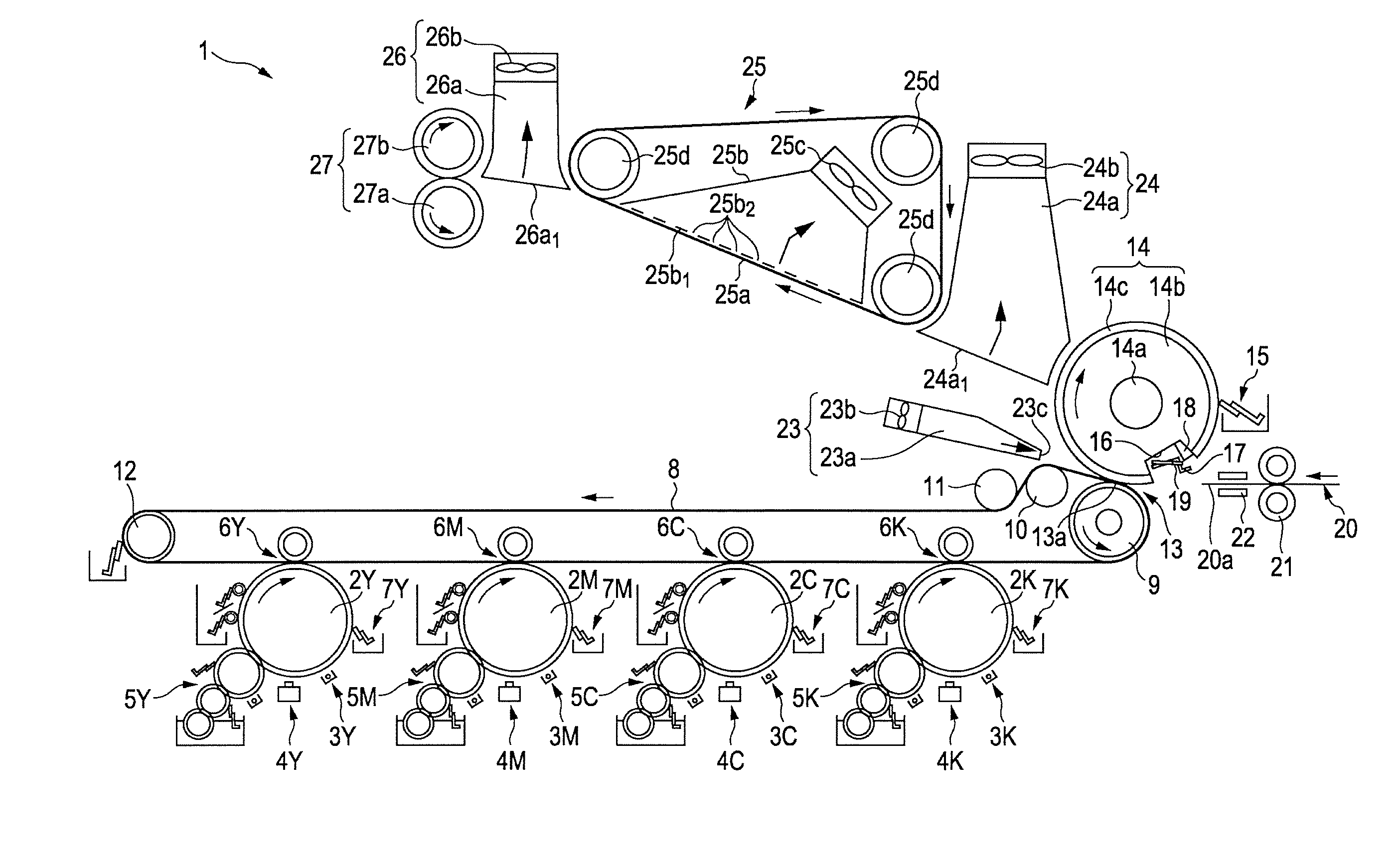
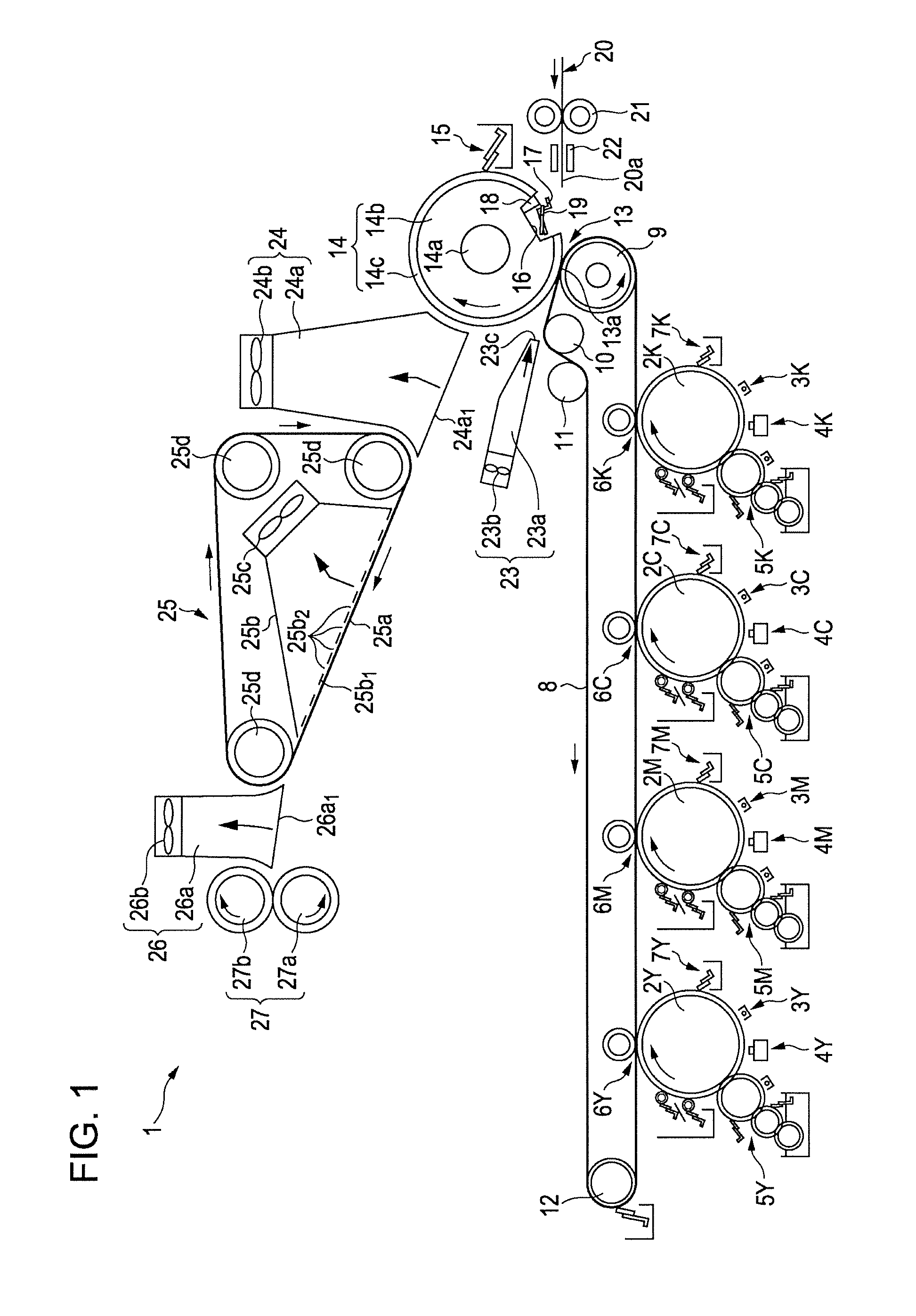
[0030]FIG. 1 is a diagram schematically and partially showing a portion of one example of an embodiment of an image forming apparatus according to the invention.

[0031]An image forming apparatus 1 of this example performs image formation by using a liquid developer containing toner and carrier liquid. As shown in FIG. 1, the image forming apparatus 1 is provided with photo conductors 2Y, 2M, 2C, and 2K which are image carriers for yellow (Y), magenta (M), cyan (C), and black (K), which are horizontally or approximately horizontally disposed in tandem. Here, in each of the photo conductors 2Y, 2M, 2C, and 2K, 2Y represents a photo conductor for yellow; 2M, a photo conductor for magenta; 2C, a photo conductor for cyan; and 2K, a photo conductor for black. Also with respect to other members, in the same way, a member for each color is represented by adding Y, M, C, or K representing each col...


PUM


Abstract

An image forming apparatus includes: an image carrier; a transfer roller that has a gripping member that grips a transfer medium; and a transfer medium transport section that has a transfer medium transport surface that sucks the transfer medium upward in a vertical direction and a contact member that contact with the transfer medium, wherein a first position where the transfer medium starts to be sucked, a second position where the transfer medium is released from the gripping member, and a third position where the transfer medium is separated from the image carrier are disposed at positions having the relationship of L<L1+L2, wherein L is the distance between the third position and the first position, L1 is the distance between the third position and the second position, and L2 is the distance between the second position and the first position.

Description

BACKGROUND[0001]1. Technical Field[0002]The present invention relates to an image forming apparatus and an image forming method, which perform transfer in a state where a transfer medium is gripped.[0003]2. Related Art[0004]In the past, with respect to an image forming apparatus, an image forming apparatus has been proposed which uses a transfer roller having a transfer medium gripping member which grips a leading end portion of a transfer medium (refer to, for example, JP-T-2000-508280). In the image forming apparatus described in JP-T-2000-508280, in a state where the leading end portion of the transfer medium is gripped by the transfer medium gripping member, the transfer medium passes through a transfer nip portion by rotation of the transfer roller, whereby an image of an image carrier is transferred to the transfer medium. According to this image forming apparatus, since the leading end portion of the transfer medium is gripped by the transfer medium gripping member, the trans...

Claims


Application Information

Patent Timeline
IPC IPC(8): G03G15/16
CPCG03G15/161G03G15/1605G03G2215/1619G03G2215/1614
Inventor TAKANO, HIDEHIRO
Owner SEIKO EPSON CORP
Why Eureka
Try Eureka