Fluid-filled vibration-damping device

a vibration-damping device and fluid-filled technology, applied in the direction of shock absorbers, jet propulsion mounting, transportation and packaging, etc., can solve the problems of dimensional error and inability to form stably gaps, and achieve the effect of stab switching

Active Publication Date: 2019-09-19
SUMITOMO RIKO CO LTD
View PDF6 Cites 2 Cited by
  • Summary
  • Abstract
  • Description
  • Claims
  • Application Information

AI Technical Summary

Benefits of technology

[0006]It is therefore one object of this invention to provide a fluid-filled vibration-damping device of novel structure capable of stably switching between a communication state and a blocked state of a communication passage by a valve, even by a smaller amplitude range.

Problems solved by technology

However, in U.S. Pat. No. 8,783,668, a gap between the switch and the inner face of the second orifice passage that face each other along the entire circumference varies due to a dimensional error of the elastic mover or the partitioner, and the like, so that a gap large enough to allow the dimensional error is required.
As a result, it is possible as well that the gap cannot be formed stably due to the dimensional error of the elastic mover or the partitioner, and the like, in a case that requires setting a smaller gap, e.g., a case where the state needs to be switched between communication and block of the second orifice passage by a smaller amplitude range.

Method used


Image

  • Fluid-filled vibration-damping device
  • Fluid-filled vibration-damping device
  • Fluid-filled vibration-damping device

Examples


Embodiment Construction

[0038]A practical embodiment of the present invention will be described below in reference to the drawings.

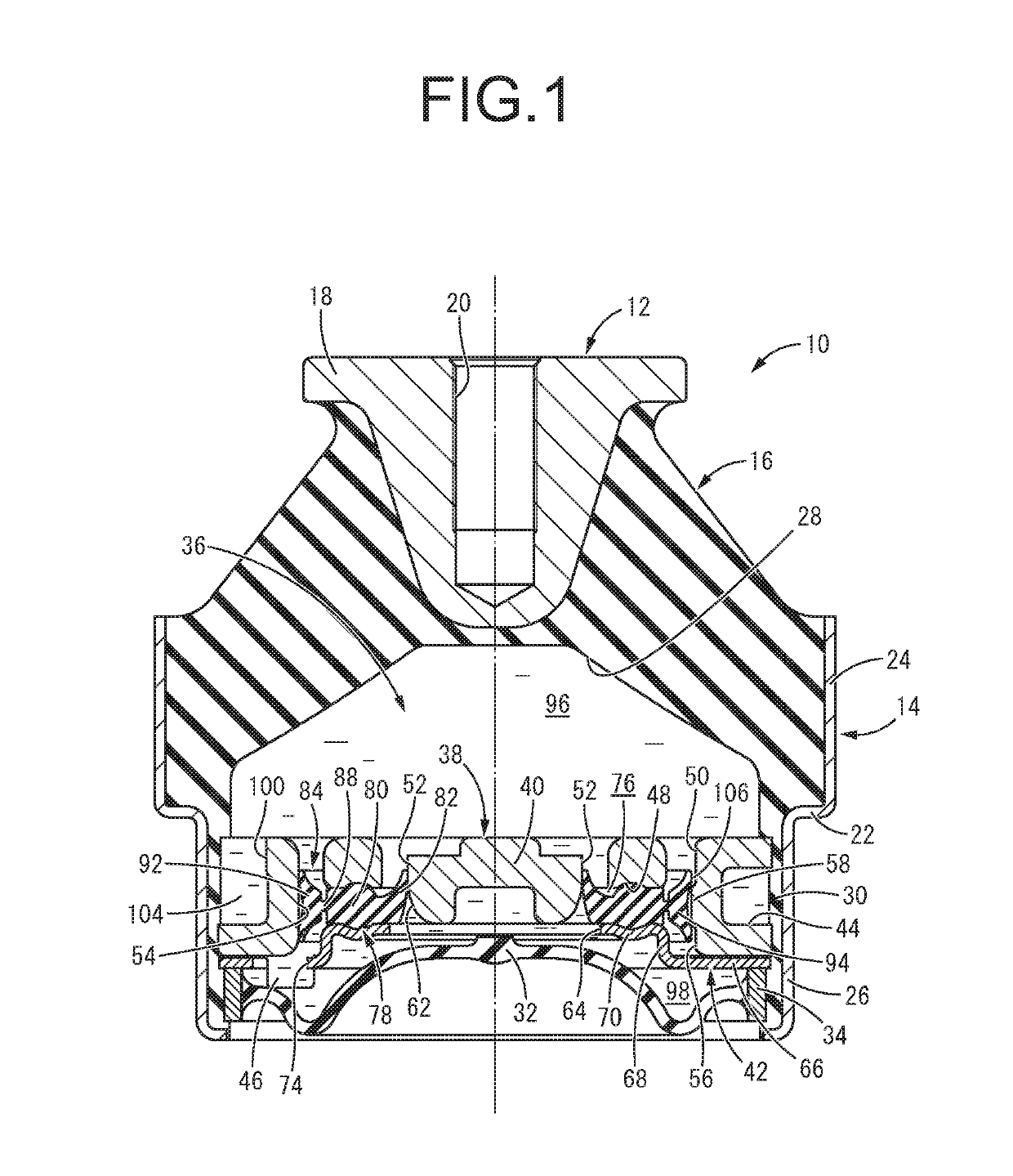
[0039]FIG. 1 shows an automotive engine mount 10 serving as a first practical embodiment of a fluid-filled vibration-damping device with a structure according to the present invention. The engine mount 10 has a structure wherein a first attachment member 12 and a second attachment member 14 are elastically connected with each other by a main rubber elastic body 16. In description hereinafter, the up-down direction means the up-down direction in FIG. 1, which is the axial direction in which the mount center axis extends and the main vibration input direction, as a general rule.

[0040]More specifically, the first attachment member 12 is made of metal, etc. and has a shape of inverted roughly truncated cone whose diameter gets gradually smaller as it goes to the lower side. A flanged portion 18 is integrally formed at the upper end of the first attachment member 12 so as to protrud...


PUM


Abstract

A fluid-filled vibration-damping device including: two elastically-connected attachment members; two liquid chambers divided by a partitioner having a storing space; an elastic mover disposed in the storing space and having a support supported by the partitioner; a positioner provided on at least one of radial inside and outside of the support, partially in a peripheral direction of the support, in abutment against a peripheral wall face of the storing space; a valve separate from the positioner in the peripheral direction, and the peripheral wall face in opposition; an axially-thin part connecting the positioner and the valve to the support in a displaceable manner; a communication passage connecting the liquid chambers formed between the peripheral wall face and the valve; and a switch configured to obstruct the communication passage by abutment of the valve against the peripheral wall face.

Description

INCORPORATED BY REFERENCE[0001]The disclosure of Japanese Patent Application No. 2018-046360 filed on Mar. 14, 2018 including the specification, drawings and abstract is incorporated herein by reference in its entirety.BACKGROUND OF THE INVENTION1. Field of the Invention[0002]The present invention relates to a fluid-filled vibration-damping device used for an automotive engine mount, etc.2. Description of the Related Art[0003]There has been known a vibration-damping device interposed between components of a vibration transmission system such as a power unit and a vehicle body to link the components to each other in a vibration-damping manner. The vibration-damping device is applied to an engine mount, or the like. Besides, as a kind of vibration-damping device, there is also proposed a fluid-filled vibration-damping device using vibration-damping effect based on flowing action of non-compressible fluid filled therein. This fluid-filled vibration-damping device has a structure wherei...

Claims


Application Information

Patent Timeline
Patent Type & Authority Applications(United States)
IPC IPC(8): F16F13/10
CPCF16F13/106B60K5/1208F16F13/266
Inventor ISHIKAWA, RYOTA
Owner SUMITOMO RIKO CO LTD
Why Eureka
Try Eureka