Motor control device

a motor control and control device technology, applied in the direction of motor/generator/converter stopper, dynamo-electric gear control, motor/generator/converter stopper, etc., can solve the problems of difficult adjustment of the plurality of motor parameters, inability to perform desired motor control, and large adjustment time, so as to facilitate the control of maximum torque or the like, the effect of reducing the quantity of calculation

Active Publication Date: 2007-03-01
III HLDG 12 LLC
View PDF1 Cites 41 Cited by
  • Summary
  • Abstract
  • Description
  • Claims
  • Application Information

AI Technical Summary

Benefits of technology

[0024] An object of the present invention is to provide a motor control device that can contribute to facilitation of adjustment of an operation parameter for obtaining a maximum torque control or the like, and / or reduction of quantity of calculations. Furthermore, it is another object to provide a motor drive system having the motor control device.
[0029] In addition, it was necessary in the conventional structure shown in FIGS. 21 and 22 to adjust an operation parameter for estimating a rotor position and an operation parameter for performing the maximum torque control. According to the structure described above, however, the adjustment of the operation parameters for performing the maximum torque control and the like can be integrated to the adjustment of the operation parameter corresponding to the q-axis inductance. In other words, the adjustment of the operation parameters for realizing the maximum torque control and the like can be facilitated, so that adjustment time can be reduced. In addition, since the sequential calculation of a value of the γ-axis component of the motor current becomes needless, quantity of calculation for the maximum torque control and the like can be reduced.
[0037] Thus, an adjustment of the operation parameter becomes easier.
[0042] Thus, a sequential calculation of a value of the γ-axis component of the motor current becomes needless, so quantity of calculation for the maximum torque control or the like can be reduced.
[0057] Thus, a smooth switching of the estimation process can be realized.
[0062] As described above, according to the motor control device and the motor drive system of the present invention, an adjustment of an operation parameter for realizing a maximum torque control or the like can be facilitated. In addition, quantity of calculation can be reduced, too.

Problems solved by technology

Therefore, if there are errors between the motor parameters (the operation parameters) that are used for calculating the specified γ-axis current value iγ* and true motor parameters, a desired motor control cannot be performed.
However, the adjustment for the plurality of motor parameters is not easy, and a lot of time is necessary for the adjustment.
Thirdly, it is necessary to perform the calculation of the specified γ-axis current value iγ* sequentially that requires a complicated calculation.
In addition, the error in the adjustment of the parameter for estimating the rotor position and the error in the adjustment of the parameter for calculating the specified γ-axis current value iγ* are affected by each other so that the adjustments become more difficult.
In addition, when the adjustments become difficult, optimization of the parameters also becomes difficult resulting in difficulty in realizing an optimal drive of the motor.
Note that the techniques described in the first patent document, the second patent document and the first non-patent document which are described above cannot solve the problem described above.

Method used


Image

  • Motor control device
  • Motor control device
  • Motor control device

Examples


first embodiment

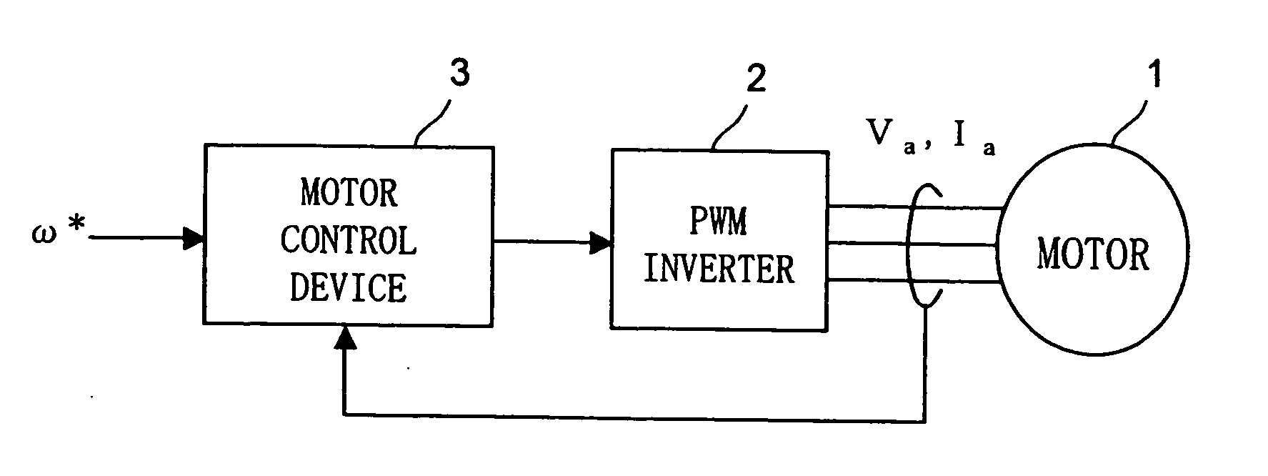
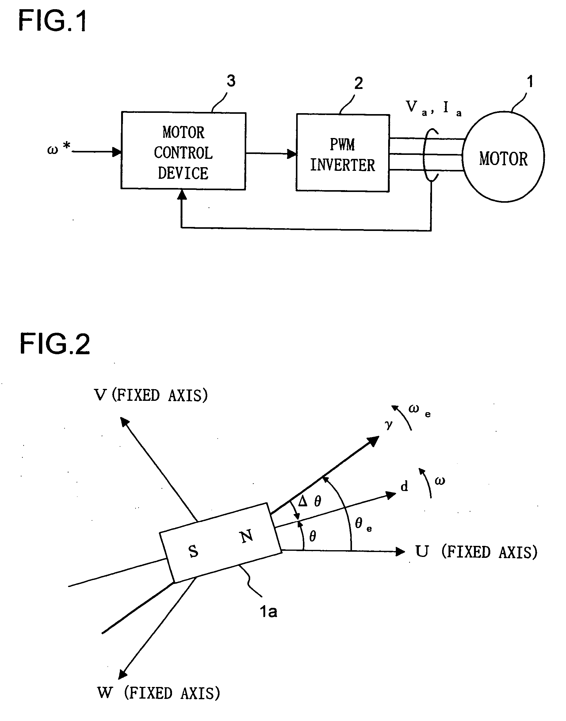
[0103] Now, embodiments of the present invention will be described in detail. To begin with, a first embodiment of the present invention will be described. FIG. 1 is a block diagram showing a general structure of a motor drive system according to a first embodiment of the present invention. Reference numeral 1 denotes a three-phase permanent magnet synchronous motor (hereinafter referred to as “motor 1” simply) including a rotor (not shown) with a permanent magnet and a stator (not shown) with an armature winding. The motor 1 is a salient pole machine (a motor having a salient pole) such as an interior permanent magnet synchronous motor.

[0104] Reference numeral 2 denotes a PWM (Pulse Width Modulation) inverter, which supplies the motor 1 with three-phase alternating voltage consisting of U-phase, V-phase and W-phase in accordance with a rotor position of the motor 1. The voltage supplied to the motor 1 is referred to as a motor voltage (or an armature voltage) Va, and current suppl...

second embodiment

[0160] Next, a second embodiment of the present invention will be described. In the descriptions of the above first embodiment, this embodiment and the following other embodiments, the same elements are denoted by the same reference numeral or the same symbol (θ, ω or the like) as long as without a special description. Therefore, overlapping description about the element denoted by the same reference numeral or the same symbol may be omitted.

[0161]FIG. 10 is a block diagram of a motor drive system according to the second embodiment. The motor drive system according to the second embodiment includes a motor 1, an inverter 2 and a motor control device 3a.

[0162] The motor control device 3a estimates a rotor position or the like of the motor 1 based on the motor current Ia, and it supplies the PWM inverter 2 with a signal for rotating the motor 1 at a desired rotation speed. This desired rotation speed is supplied from a CPU (Central Processing Unit) or the like (not shown) to the mot...

third embodiment

[0235] In addition, it is possible to modify the structure of the motor control device 3a shown in FIG. 14 like the motor control device 3b shown in FIG. 19. The embodiment after this modification is a third embodiment of the present invention. The motor control device 3b has a structure in which the estimator 40 of the motor control device 3a in FIG. 14 is replaced with a position / speed estimator 45 (hereinafter referred to as an estimator 45 simply), a θm calculator 46 and a computing unit 47. Except for this replacement, the motor control device 3b and the motor drive system in FIG. 19 are similar to the motor control device 3a and the motor drive system in FIG. 14. Description of structures and operations of the similar parts will be omitted.

[0236] The estimator 45 estimates a phase of the d-axis viewed from the U-phase by using the iγ, iδ, vγ* and vδ*, and it outputs the estimated value as θdqe. In addition, the estimator 45 calculates the estimated motor speed ωe similarly to...


PUM


Abstract

A motor control device includes an estimator for estimating a rotor position of a motor having a salient pole by using a value corresponding to a q-axis inductance of the motor as an operation parameter where an estimated axes for the control corresponding to d-q axes are γ-δ axes, and a controller for controlling the motor based on the estimated rotor position. The estimator generates a deviation between a d-axis and a γ-axis by performing the estimation of the rotor position based on a value between a real q-axis inductance and a real d-axis inductance of the motor adopted as the operation parameter. The controller controls the motor so that a γ-axis component of a motor current supplied to the motor is maintained to be a predetermined value of zero or close to zero regardless of a value of a δ-axis component of the motor current.

Description

[0001] This nonprovisional application claims priority under 35 U.S.C. §119(a) on Patent Application No. 2005-246305 filed in Japan on Aug. 26, 2005, Patent Application No. 2006-043398 filed in Japan on Feb. 21, 2006, and Patent Application No. 2006-177646 filed in Japan on June 28, 2006, the entire contents of which are hereby incorporated by reference. BACKGROUND OF THE INVENTION [0002] 1. Field of the Invention [0003] The present invention relates to a motor control device for controlling an operation of a motor. The present invention also relates to a motor drive system including this motor control device. [0004] 2. Description of Related Art [0005] Conventionally, a motor control device without a rotor position sensor (a position sensor-less motor control device) is developed. This a motor control device estimates a rotor position in a motor without a rotor position sensor and controls the motor base on the estimated rotor position. FIG. 21 shows an example of a block diagram f...

Claims


Application Information

Patent Timeline
Patent Type & Authority Applications(United States)
IPC IPC(8): H02P27/04H02P21/00H02P21/13H02P21/18H02P21/22H02P21/24H02P21/28H02P23/12H02P23/16H02P25/022H02P25/026
CPCH02P21/146H02P2203/05H02P2207/05H02P2203/11H02P2203/09H02P21/18
Inventor TOMIGASHI, YOSHIOHIDA, HAJIME
Owner III HLDG 12 LLC
Why Eureka
Try Eureka