

Three-dimensional display method and device therefor
- Summary
- Abstract
- Description
- Claims
- Application Information
AI Technical Summary
Benefits of technology
Problems solved by technology
Method used
Image

Examples
Embodiment Construction
[0048] Embodiments of the present invention will be described below in detail.
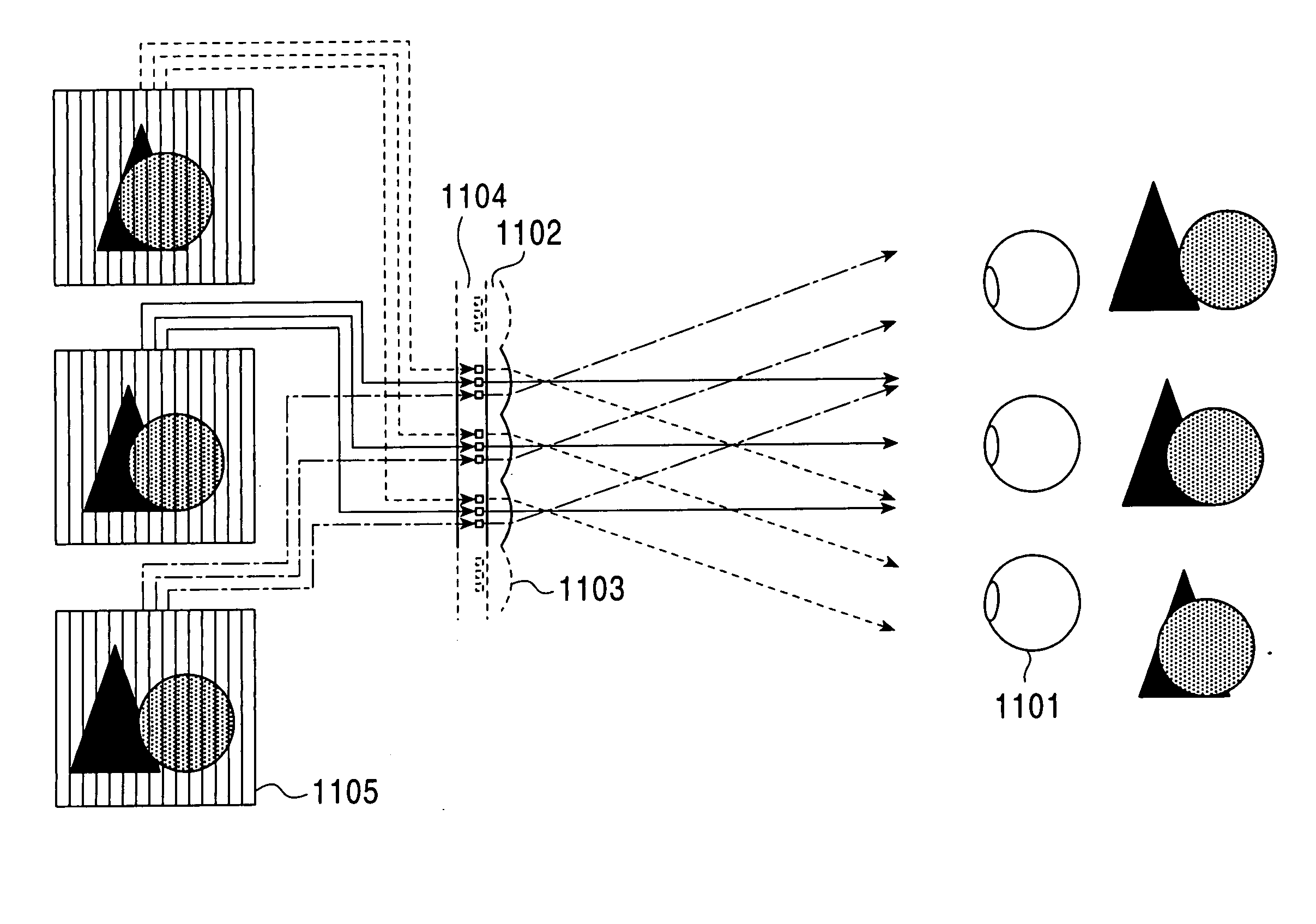
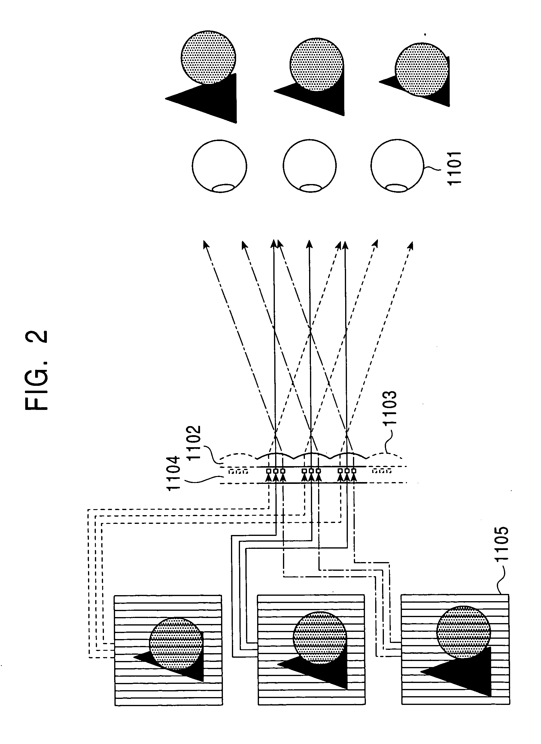
[0049] At first, terms, which will be used in the description below, are described. An emitting angle of light emitted from a display plane of an image is called as a display angle; when the emitting angle of light is limited within an angular range, this angular range is called as a display angular range; wherein the emitting angle is to be measured from the normal line of an image plane. That is, when the image plane is viewed, an image can be viewed only within the display angular range. The central axial direction of the display angular range is called as a display direction. Also, a two-dimensional image display and a light source array used for image display are collectively called as an image generating source.
[0050]FIG. 5 is an explanatory drawing of high-density horizontal parallax image display produced by amalgamation between two-dimensional arrangement of display angular ranges of a plurality...
PUM
 Abstract
Description
Claims
Application Information