
Method and apparatus for improving quality of depth image

a technology of depth image and quality enhancement, applied in image enhancement, image analysis, instruments, etc., can solve problems such as difficulty in acquiring high-quality depth images, and achieve the effect of enhancing the quality of the depth image acquired

Inactive Publication Date: 2013-11-19
ELECTRONICS & TELECOMM RES INST
View PDF23 Cites 23 Cited by
  • Summary
  • Abstract
  • Description
  • Claims
  • Application Information

AI Technical Summary

Benefits of technology

The present invention provides a method and apparatus for improving the quality of depth images. This involves setting a disparity value and an intensity difference value to enhance the quality of the depth image. The method also includes receiving a multi-view image, a current depth image frame, and a previous depth image frame, and setting an intensity difference value corresponding to a specific disparity value and a disparity value range. The technical effect of this invention is to improve the accuracy and consistency of depth images, which can be useful in various applications such as autonomous vehicles and augmented reality.

Problems solved by technology

Although the TOF method can create a depth image in real time, it is difficult to acquire a high-quality depth image due to irregular reflection or noise which occurs in bright environments.

Method used


Image

  • Method and apparatus for improving quality of depth image
  • Method and apparatus for improving quality of depth image
  • Method and apparatus for improving quality of depth image

Examples


Embodiment Construction

[0020]Exemplary embodiments of the present invention will be described below in more detail with reference to the accompanying drawings. The present invention may, however, be embodied in different forms and should not be constructed as limited to the embodiments set forth herein. Rather, these embodiments are provided so that this disclosure will be thorough and complete, and will fully convey the scope of the present invention to those skilled in the art. Throughout the disclosure, like reference numerals refer to like parts throughout the various figures and embodiments of the present invention.

[0021]As described above, a depth image may be acquired using an active method and a passive method. When a depth image is acquired using the active method such as a TOF method, a high-quality depth image may not be acquired.

[0022]Meanwhile, as described above, the passive method acquires a depth value by using multi-view images. This will be briefly described below. A process of matching ...


PUM


Abstract

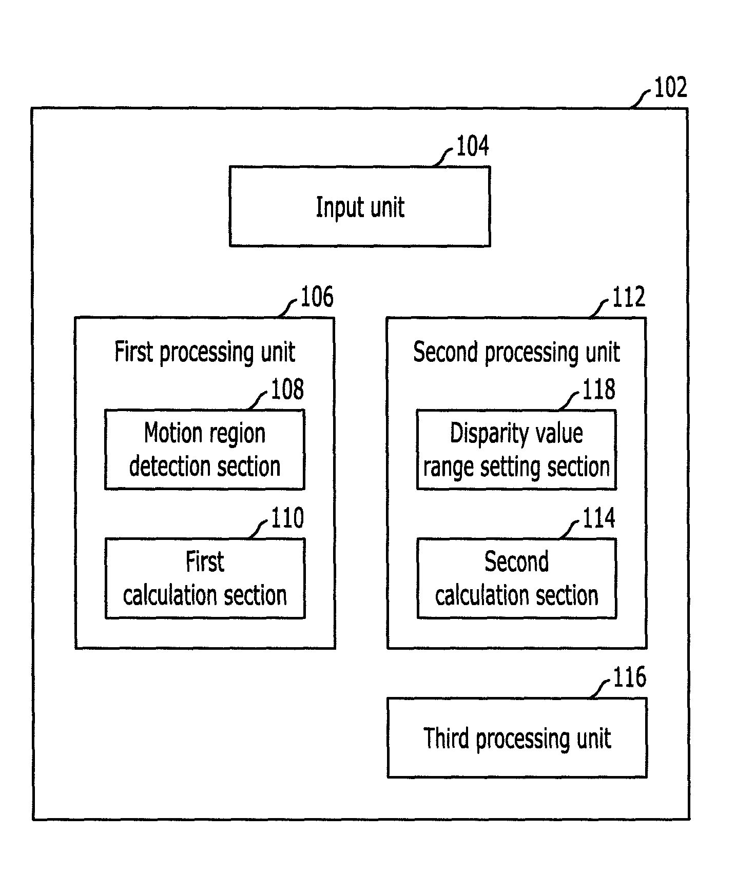
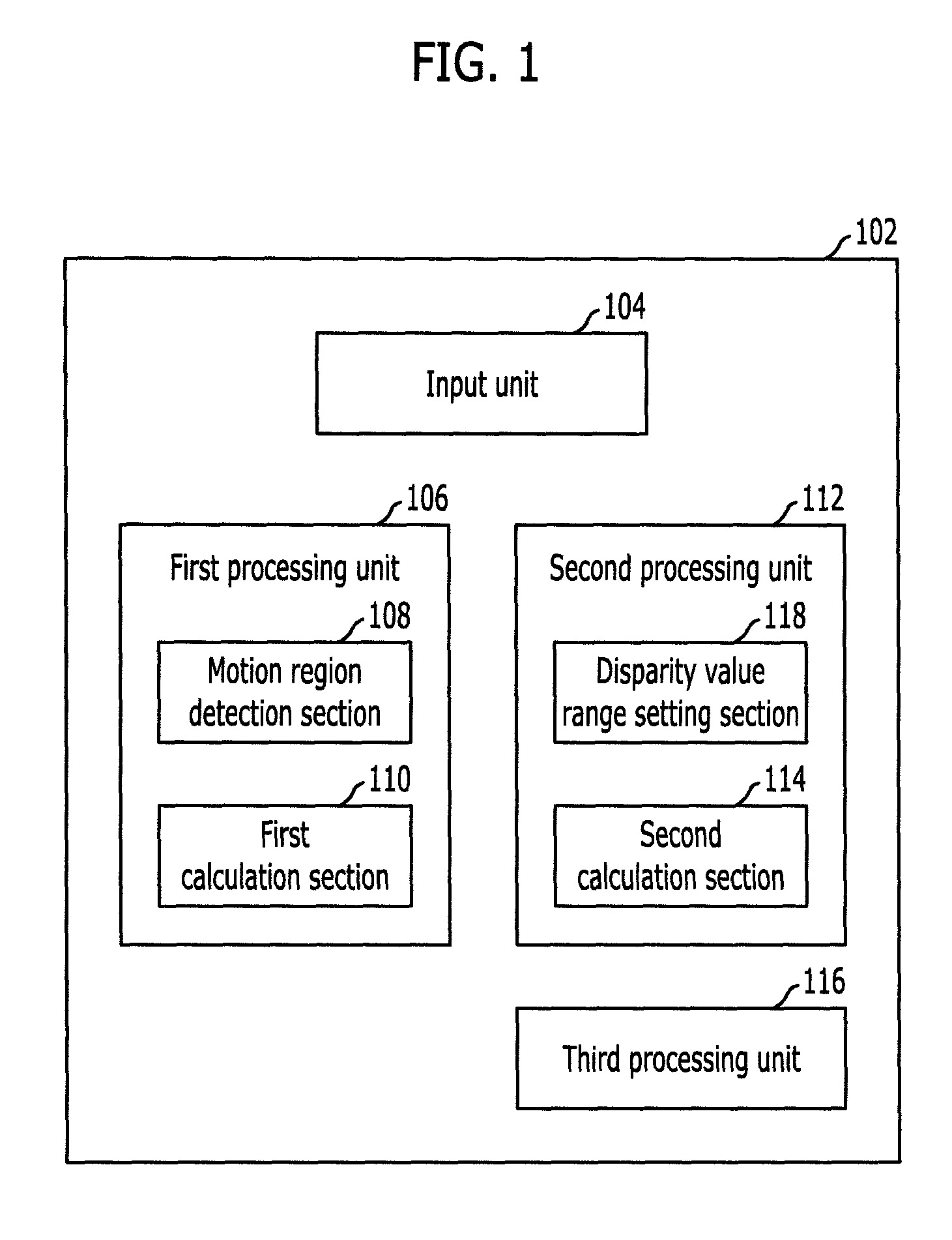
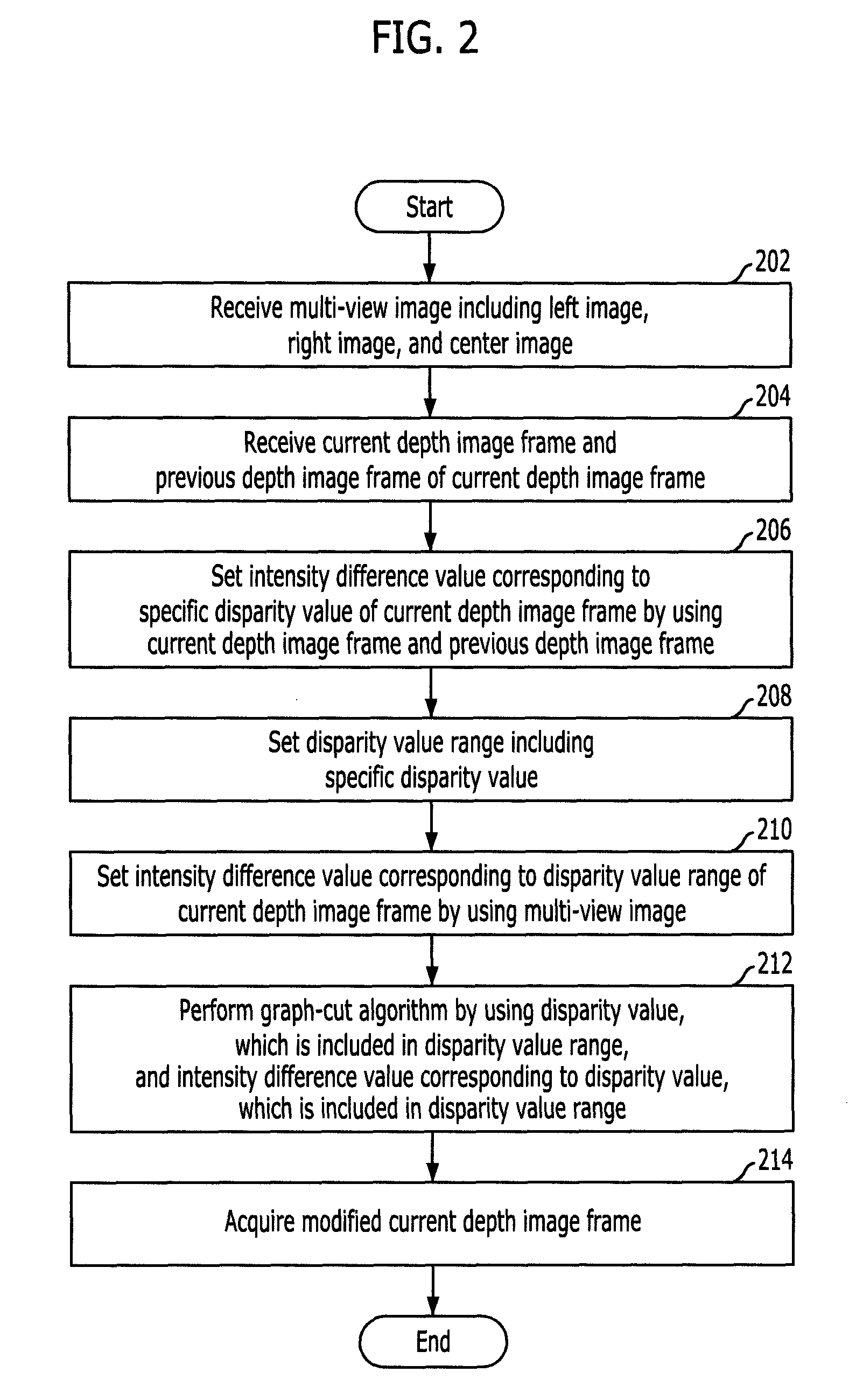
A method and apparatus for enhancing quality of a depth image are provided. A method for enhancing quality of a depth image includes: receiving a multi-view image including a left image, a right image, and a center image; receiving a current depth image frame and a previous depth image frame of the current depth image frame; setting an intensity difference value corresponding to a specific disparity value of the current depth image frame by using the current depth image frame and the previous depth image frame; setting a disparity value range including the specific disparity value; and setting an intensity difference value corresponding to the disparity value range of the current depth image frame by using the multi-viewpoint image.

Description

CROSS-REFERENCE(S) TO RELATED APPLICATIONS[0001]The present application claims priority of U.S. Provisional Patent Application Nos. 61 / 147,807 and 61 / 169,539, filed on Jan. 28, 2009, and Apr. 15, 2009, which are incorporated herein by reference in its (their) entirety.BACKGROUND OF THE INVENTION[0002]1. Field of the Invention[0003]Exemplary embodiments of the present invention relate to a method and apparatus for enhancing quality of a depth image; and, more particularly, to a method and apparatus for further enhancing quality of a depth image which has already been acquired.[0004]2. Description of Related Art[0005]As interest in three-dimensional (3D) images has increased in recent years, much research has been conducted on 3D image technologies. In order to render a 3D image, it is necessary to acquire 3D information or depth information of an object or scene.[0006]Unlike a general video image, a depth image refers to an image which includes depth information of an object or scene...

Claims


Application Information

Patent Timeline
Patent Type & Authority Patents(United States)
IPC IPC(8): G06K9/00
CPCG06T5/50G06T2207/10028
Inventor BANG, GUNUM, GI-MUNCHANG, EUN-YOUNGKIM, TAEONEHUR, NAM-HOKIM, JIN-WOONGLEE, SOO-IN
Owner ELECTRONICS & TELECOMM RES INST
Learn More