Speed-Change Transmission Apparatus

a transmission apparatus and speed-change technology, applied in the direction of fluid gearing, transportation and packaging, gearing, etc., can solve the problem that the clutch cannot be switched over smoothly

a transmission apparatus and speed-change technology, applied in the direction of fluid gearing, transportation and packaging, gearing, etc., can solve the problem that the clutch cannot be switched over smoothly

US20080214351A1Active Publication Date: 2008-09-04KUBOTA LTD

Image

  • Speed-Change Transmission Apparatus
  • Speed-Change Transmission Apparatus
  • Speed-Change Transmission Apparatus

Examples


Embodiment Construction

[0031]Next, embodiments of the present invention will be described with reference to the accompanying drawings.

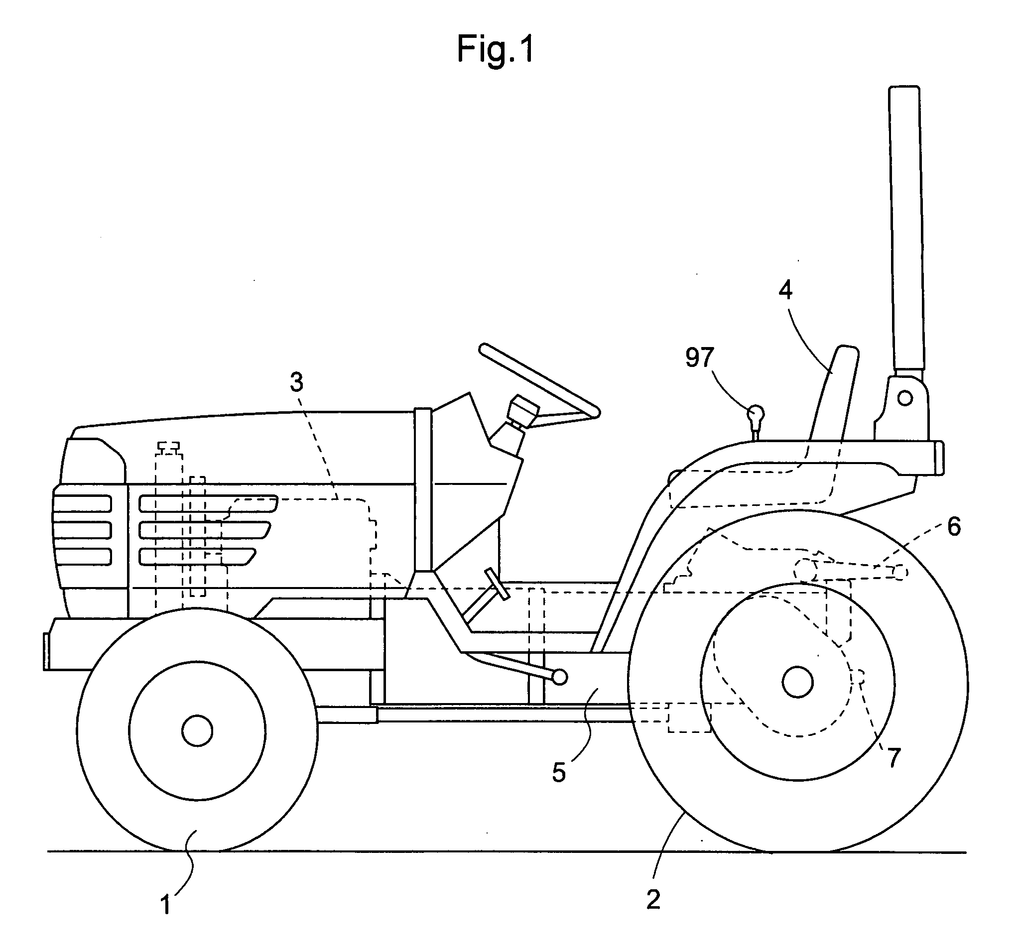
[0032]As shown in FIG. 1, a tractor, as an example of a utility vehicle, includes a vehicle frame mounting a pair of right and left steerable and drivable front wheels 1, a pair of right and left drivable rear wheels 2, an engine section having an engine 3 mounted at a front portion of the vehicle body, and a driving section having a driver's seat 4 at a rear portion of the vehicle body. A rear transmission case 5 constitutes a rear portion of the vehicle frame. Rearwardly of and opposed lateral sides of this rear transmission case 5, there are mounted lift arms 6 vertically pivotable. To a rear wall portion of the rear transmission case 5, there is attached a power takeoff (PTO) shaft 7.

[0033]This tractor allows attachment, to its rear vehicle body portion, of a rotary plow implement (not shown) liftable up / down via a link mechanism (not shown) utilizing the pair of right ...


PUM


Abstract

A speed-change transmission apparatus for effecting a speed-changing on an engine drive force with utilizing a continuously variable speed-change device, a plurality of planetary transmission mechanisms and a plurality of clutches is constructed to be capable of effecting the speed-changing operation smoothly, regardless of a centrifugal force generated in the clutches. An output from the continuously variable speed-change device and a drive force from the engine are combined by a planetary transmission section. The drive force from this planetary transmission section is transmitted via a clutch section to an output shaft. First, second, third and fourth clutches of the clutch section are configured to be switched over respectively between an engaged condition and a disengaged condition, as clutch members are engaged with or disengaged from output side rotational members.

Description

FIELD OF THE INVENTION[0001]This invention relates to a speed-change transmission apparatus, more particularly to a speed-change transmission apparatus having a continuously variable speed-change device and a planetary transmission section.BACKGROUND ART[0002]Examples of such conventional speed-change transmission apparatus are disclosed in e.g. Patent Document 1 and Patent Document 2.[0003]The speed-change transmission apparatus disclosed in Patent Document 1 includes a unit having a variable displacement hydrostatic unit 4 and a fixed displacement hydrostatic unit 6, a planetary transmission section having a first planetary gear set 9, a second planetary gear set 10 and a planetary gear set 22 and a clutch section having a coupling 27, a coupling 32, a coupling 35 and a coupling 39.[0004]The speed-change transmission apparatus disclosed in Patent Document 2 includes a hydraulic unit 4, a summator gear 10, a clutch section having clutches K1, K2, a planetary transmission section ha...

Claims


Application Information

Patent Timeline
04 Sep 2008
Publication
US20080214351A1
IPC
F16H3/44
CPC
F16H47/04; F16H2037/088; F16H2200/0095; F16H2200/0043; F16H2037/0886
Inventors
KATAYAMA, YOSHIYUKI; UEDA, YOSHIHIRO