
Reactor

a reactor and reactor technology, applied in the field of reactors, can solve the problems of increasing the loss of the reactor owing to the generated hea

Active Publication Date: 2013-11-28
SUMITOMO ELECTRIC IND LTD
View PDF8 Cites 29 Cited by
  • Summary
  • Abstract
  • Description
  • Claims
  • Application Information

AI Technical Summary

Benefits of technology

The present invention is a small reactor that can accurately measure the temperature of its coil. The technical effect of this invention is the provision of a small but efficient tool for measuring the temperature of a coil, which can help in various manufacturing processes where the temperature of the coil needs to be controlled.

Problems solved by technology

When the coil receives electricity and generates heat, the loss of the reactor increases owing to the generated heat.

Method used


Image

  • Reactor
  • Reactor
  • Reactor

Examples


first embodiment

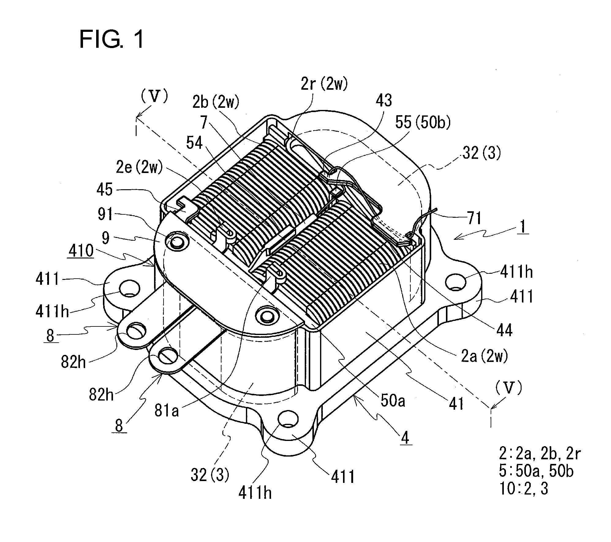
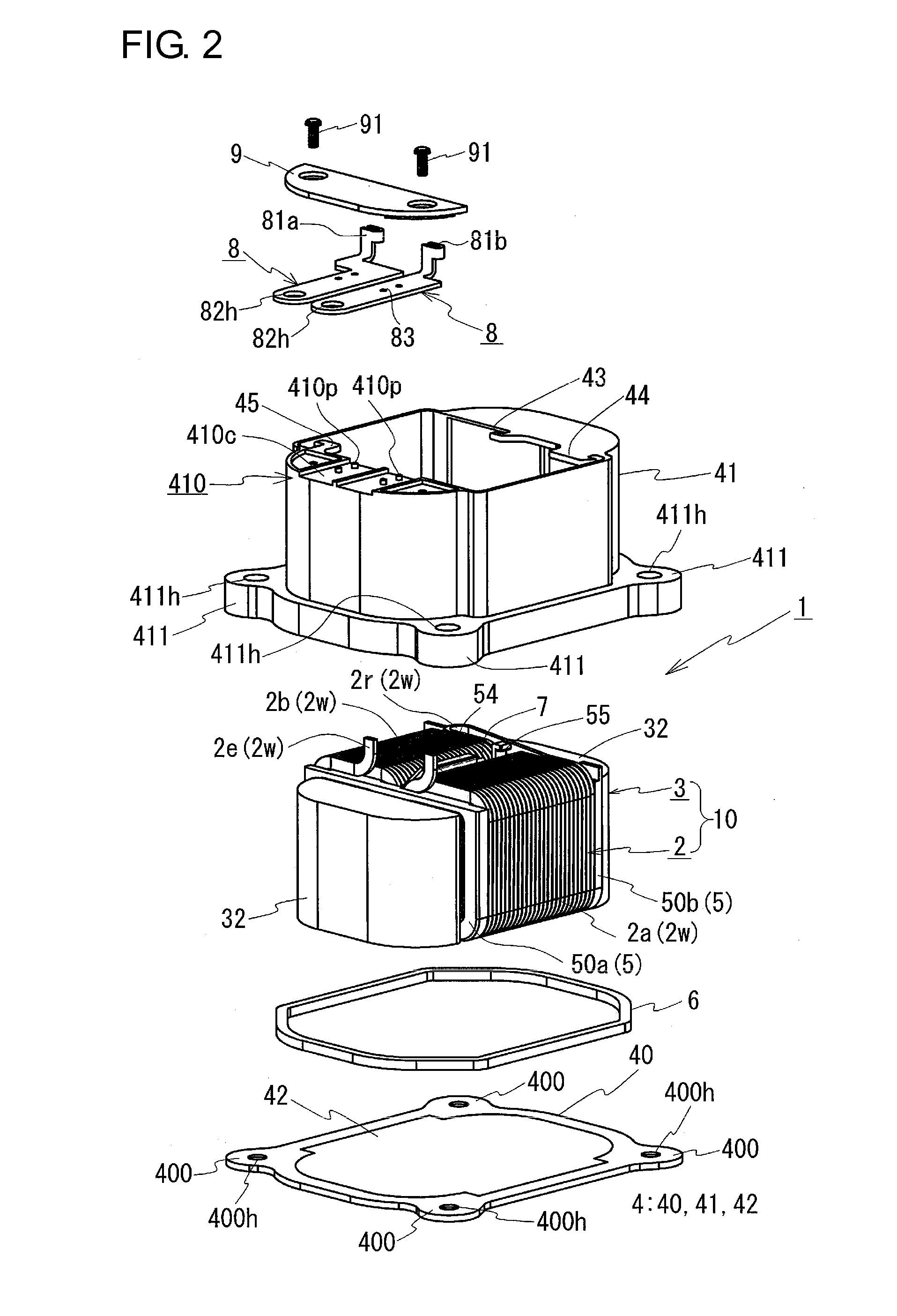
[0048]A reactor 1 according to a first embodiment of the present invention will now be described with reference to FIGS. 1 to 5. In the figures, the same reference symbols denote components having the same names. In the following description, an installation side at which the reactor is installed is referred to as a bottom side, and the side opposite thereto is referred to as a top side.

[0049]>

[0050]The reactor 1 includes a coil 2 including a pair of coil elements 2a and 2b; a magnetic core 3 including a pair of inner core portions 31 (FIG. 3) disposed in the respective coil elements 2a and 2b and outer core portions 32 that connect the inner core portions 31 to form a closed magnetic circuit; and a temperature sensor 7 that measures the temperature of the coil 2. The reactor 1 of this example further includes a case 4 that houses an assembly 10 of the coil 2 and the magnetic core 3 and an insulator 5 interposed between the coil 2 and the magnetic core 3. The case 4 is a box-shaped ...

second embodiment

[0193]The reactor according to the first embodiment or any of the first to fourth modifications may be used as, for example, a component of a converter mounted on a vehicle or the like, or a component of a power conversion device including the converter.

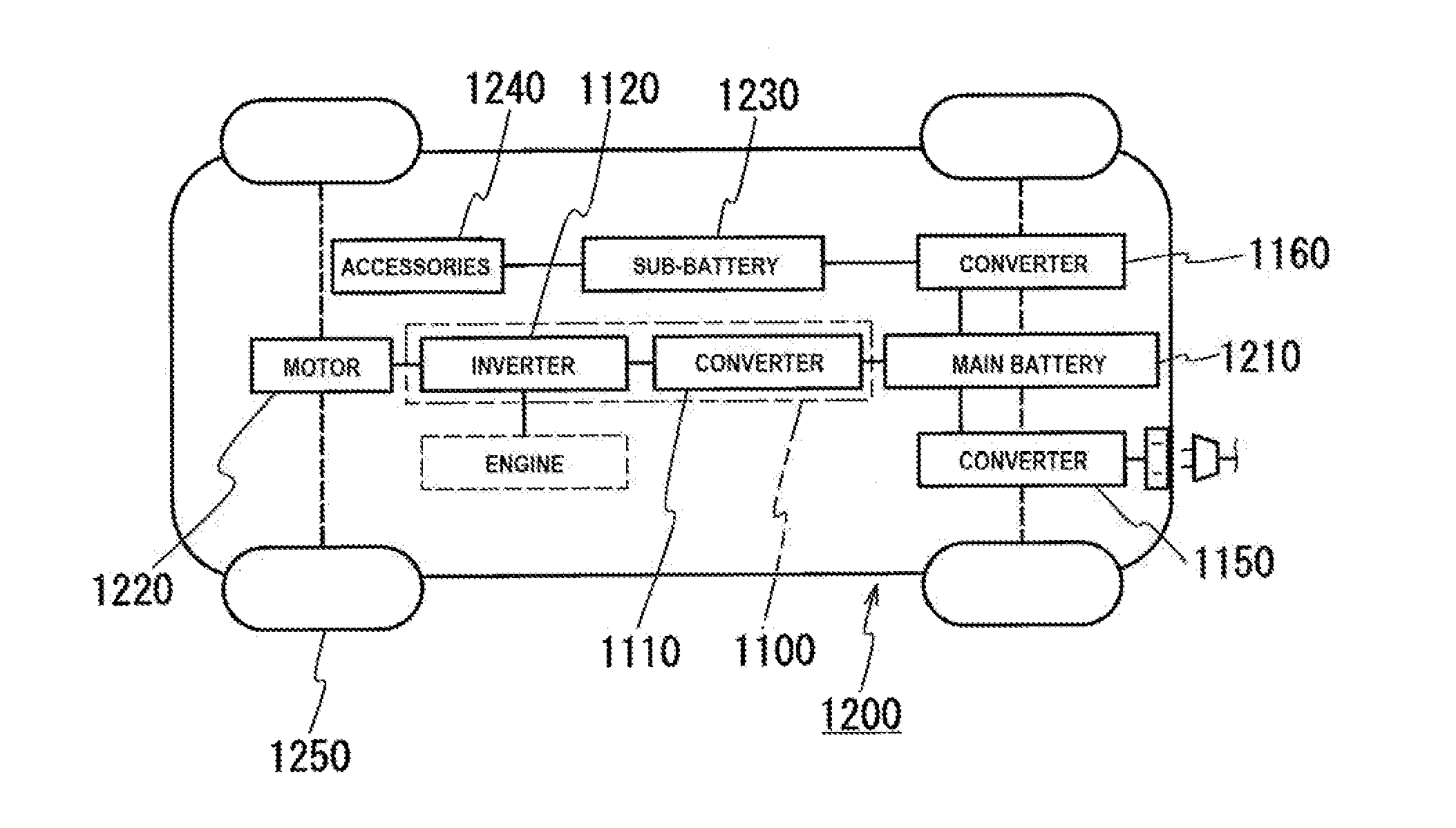
[0194]For example, as illustrated in FIG. 7, a vehicle 1200, which is a hybrid vehicle or an electric vehicle, includes a main battery 1210, a power conversion device 1100 connected to the main battery 1210, and a motor (load) 1220 driven by power supplied from the main battery 1210 and used to drive the vehicle 1200. The motor 1220 is typically a three-phase alternating current motor. The motor 1220 drives wheels 1250 when the vehicle 1200 is driven and functions as a generator during regeneration. In the case where the vehicle 1200 is a hybrid vehicle, the vehicle 1200 includes an engine in addition to the motor 1220. Although an inlet is illustrated in FIG. 7 as a charging portion of the vehicle 1200, a plug may instead be provide...


PUM

PropertyMeasurementUnit
temperatureaaaaaaaaaa
thicknessaaaaaaaaaa
thicknessaaaaaaaaaa

Abstract

A small reactor capable of appropriately measuring the temperature of a coil is provided. The reactor includes a coil 2 including a pair of coil elements 2a and 2b and a magnetic core including a pair of inner core portions 31 disposed in the respective coil elements 2a and 2b and outer core portions that connect the inner core portions 31 to form a closed magnetic circuit. Each of the coil elements 2a and 2b has an end face shape having a rounded corner portion 21, which is a corner portion of a rectangle that is rounded. A temperature sensor 7 is disposed in a trapezoidal space between the rounded corner portions 21 of the coil elements 2a and 2b that face each other. The temperature sensor 7 is pressed so as to contact the rounded corner portions 21 by the sensor holder portion 54 provided on an insulator, and is capable of appropriately measuring the temperature of the coil 2. When the temperature sensor 7 is disposed in a region in which the inner core portions 31 are not disposed in the respective coil elements 2a and 2b, the coil elements 2a and 2b can be positioned near each other and the size of the reactor can be reduced.

Description

TECHNICAL FIELD[0001]The present invention relates to a reactor for use as a component of a power conversion device, such as an on-vehicle DC-DC converter mounted in a vehicle, such as a hybrid vehicle, a converter including the reactor, and a power conversion device including the converter. More particularly, the present invention relates to a small reactor capable of appropriately measuring a temperature of a coil.BACKGROUND ART[0002]A reactor is one of components of a circuit that performs an operation of increasing or reducing a voltage. For example, Patent Literature (PTL) 1 discloses a reactor included in a converter mounted in a vehicle, such as a hybrid vehicle. The reactor includes, for example, a coil, a ring-shaped magnetic core, a case, and sealing resin (secondary resin part). The coil includes a pair of coil elements that are arranged next to each other. The magnetic core includes a pair of pillar-shaped inner core portions (coil winding portions) that are inserted thr...

Claims


Application Information

Patent Timeline
Patent Type & Authority Applications(United States)
IPC IPC(8): H01F27/40H02M7/44G05F1/618
CPCH01F27/402G05F1/618H02M7/44H01F37/00H01F2027/406H01F27/02H01F27/324
Inventor YOSHIKAWA, KOUHEI
Owner SUMITOMO ELECTRIC IND LTD
Features
  • Generate Ideas
  • Intellectual Property
  • Life Sciences
  • Materials
  • Tech Scout
  • Unparalleled Data Quality
  • Higher Quality Content
  • 60% Fewer Hallucinations
Learn More