
Video output device and video output method

a video output device and output method technology, applied in the field of video output devices and video output methods, can solve the problems of inability to recognize the user and difficult to read the information displayed by the user, and achieve the effect of preventing the loss of information that the user wants to know

Active Publication Date: 2013-12-05
PANASONIC INTELLECTUAL PROPERTY CORP OF AMERICA
View PDF3 Cites 8 Cited by
  • Summary
  • Abstract
  • Description
  • Claims
  • Application Information

AI Technical Summary

Benefits of technology

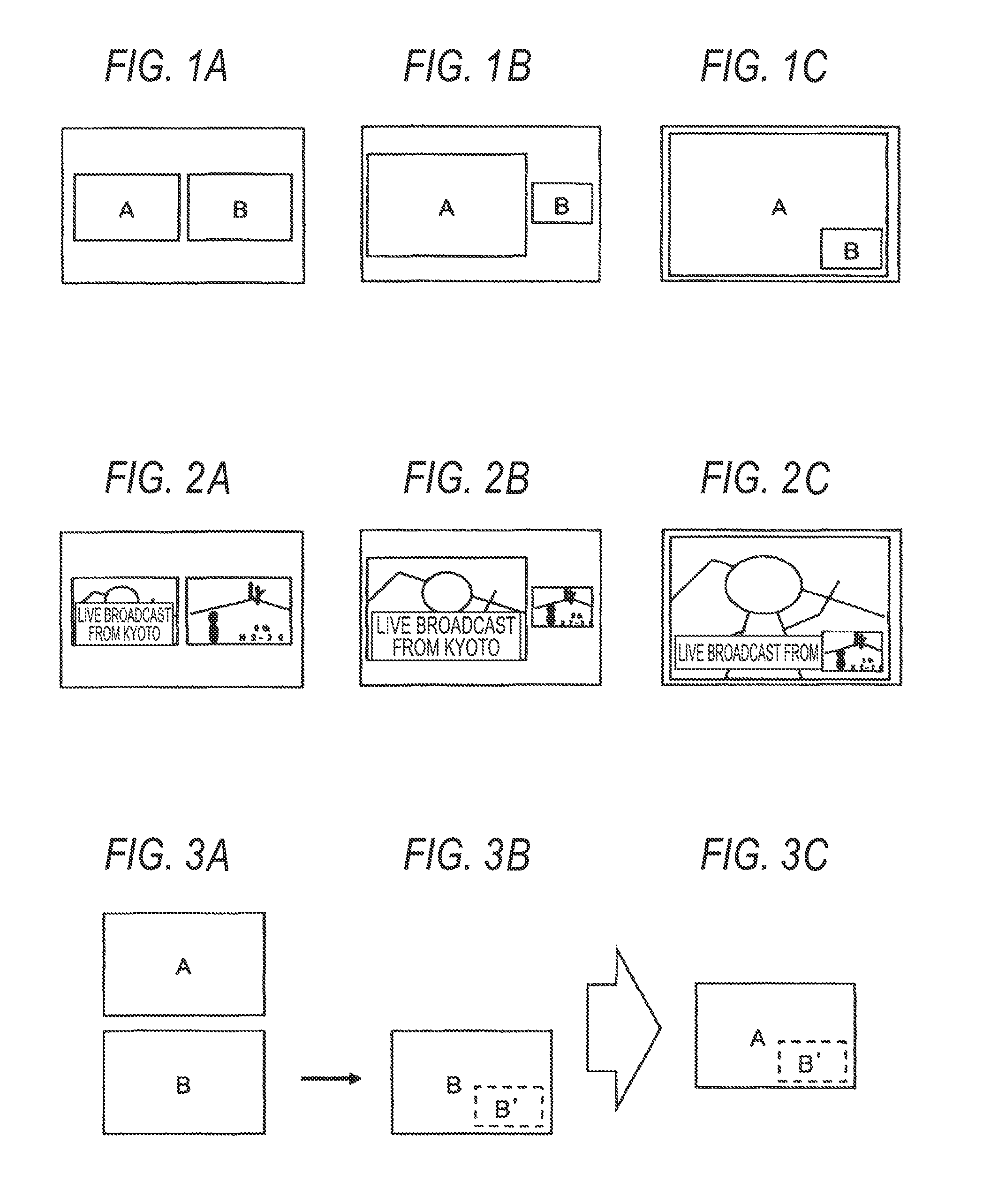
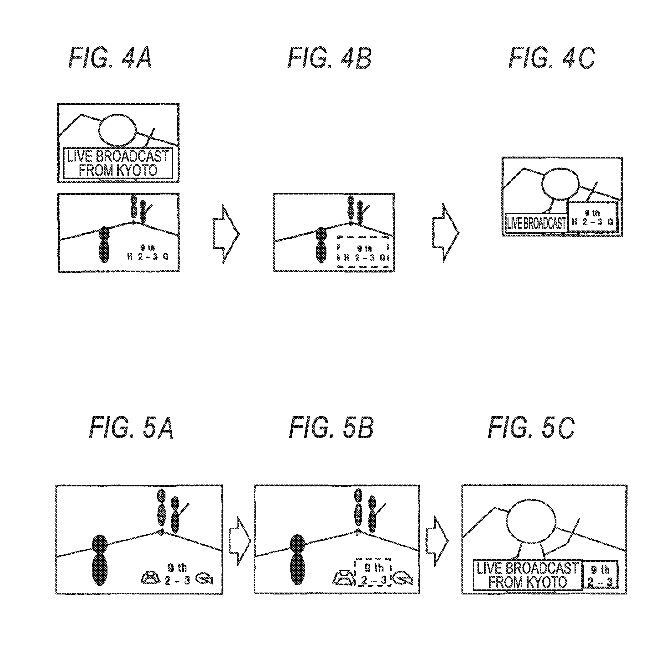
[0021]According to the video output device and the video output method according to the invention, the display form of supplemental information can be changed in response to the scaling factor of the display size of input video. Thus, if screen division of a plurality of input video images is performed, the portion where crush of a character or a symbol in input video occurs can be complemented by supplemental information and loss of information that the user wants to know can be prevented.

Problems solved by technology

At this time, the displayed information is hard to read by the user and cannot be recognized by the user; this is a problem.

Method used


Image

  • Video output device and video output method
  • Video output device and video output method
  • Video output device and video output method

Examples


first embodiment

[0053]FIG. 6 is a block diagram to show a video output device of a first embodiment and its relevant devices. To begin with, a processing outline until the video output device displays input video on a display will be discussed. As shown in FIG. 6, an image output device 100 includes an input section 101, a terminal control section 102, a screen configuration management section 103, a video input section 104, an application processing section 105, a screen generation section 106, a combining section 107, an output section 108, an area determination section 112, a supplemental information storing section 113, and a supplemental information display determination section 115.

[0054]The input section 101 receives a control instruction signal from a remote control device (simply called “remote controller”) attached to the image output device 100 or an external connection device, etc., and transfers the signal to the terminal control section 102. The terminal control section 102 sends an i...

second embodiment

[0138]The first embodiment shows the case wherein each character area and each object area are extracted from input video and if each character area overlaps an object area, area is cut out as one supplemental information and the supplemental information is superposed for display on an empty area of the screen layout configuration managed by the screen configuration management section 103 in response to the scaling factor of input video. In a second embodiment, the case where a video output device 100 acquires and displays supplemental information from an external server through a network 600 in addition to supplemental information extracted by area determination section 112 of the video output device 100 will be discussed.

[0139]In the embodiment, processing of acquiring and displaying supplemental information from an external server will be discussed with reference to FIGS. 28 to 30. FIG. 28 is a block diagram to show the video output device of the second embodiment and its relevan...


PUM


Abstract

A video output method and device includes utilizing a supplemental information storing section to determine whether or not an object area exists in the proximity of at least one character area, cuts out a video on a supplemental information area when the object area exists, and stores the video on the supplemental information area as supplemental information including the object area. A supplemental information display determination section determines whether or not the supplemental information stored by the supplemental information storing section is displayed in addition to an input video based on a screen configuration managed by the screen configuration management section. The supplemental information display determination section determines whether the supplemental information is displayed based on a size of a character included in a character area in the input video which changes in response to the scaling managed by the screen configuration management section.

Description

[0001]This application is a division of U.S. patent application Ser. No. 12 / 747,019 filed Jun. 9, 2010 which is incorporated herein by reference in its entirety.TECHNICAL FIELD[0002]This invention relates to a video output device and a video output method for changing the display form of supplemental information in response to the scaling factor of the display size of input video.BACKGROUND ART[0003]Generally, a device for receiving a broadcast program provided by a TV broadcast station, a cable TV station, etc., processes a reception signal and outputs video. Hereinafter, the device will be called “video output device.” The video output destination is a display installed in the video output device or an external display connected to the video output device through a communication member of a cable, etc. At this time, to meet the demand of the user who wants to view more than one program at the same time, for example, “two-screen mode” of displaying two input video images on two div...

Claims


Application Information

Patent Timeline
Patent Type & Authority Applications(United States)
IPC IPC(8): H04N5/445H04N5/44H04N7/16H04N7/24
CPCH04N5/44591G09G5/12G09G5/14G09G5/22G09G5/32G09G2340/0414G09G2340/0421G09G2340/0471G09G2340/0478G09G2340/12G09G2340/125G09G2370/042H04N7/0122H04N7/163H04N21/235H04N21/4312H04N21/4314H04N21/4316H04N21/435H04N21/47H04N21/4858H04N21/488
Inventor YUKI, YASUHIRO
Owner PANASONIC INTELLECTUAL PROPERTY CORP OF AMERICA
Learn More