Method for radio communication in a wireless local area network and transceiving device

Inactive Publication Date: 2011-04-28
AIRGAIN INC
View PDF14 Cites 8 Cited by
  • Summary
  • Abstract
  • Description
  • Claims
  • Application Information

AI Technical Summary

Benefits of technology

The purpose of the present invention consists in creating such a method for radio communication in a WLAN and developing such a WLAN transceiving device, which while having the advantages offered by the reference system would enable one to incr

Problems solved by technology

At the same time the employment of the omnidirectional radiation of signals imposes a limitation on the network range determined predominantly by the radiation power of a transceiving device and sensitivity of its receiver, which parameters as a rule cannot be significantly improved for WLAN users.
In addition, the known method doesn't ensure sufficient reliability of radio communication due to the possibility of emergence of multipath interference in the signal reception point and due to the signal fading effect.
At the same time employment of an omnidirectional antenna in the device limits the network range determined predominantly by the radiation power of a transceiving device and sensitivity of its receiver, which parameters as a rule cannot be significantly improved for mobile WLAN users that are powered from a self-contained source.
In addition, the known device doesn't ensure sufficient reliability of radio communication due to the possibility of emergence of multipath interference in the signal reception point and due to the signal fading effect.
While enabling one to minimize the influence of signal fading the known method still has the same limitations on the network range that are inherent to methods employing omnidirect

Method used


Image

  • Method for radio communication in a wireless local area network and transceiving device
  • Method for radio communication in a wireless local area network and transceiving device
  • Method for radio communication in a wireless local area network and transceiving device

Examples


Embodiment Construction

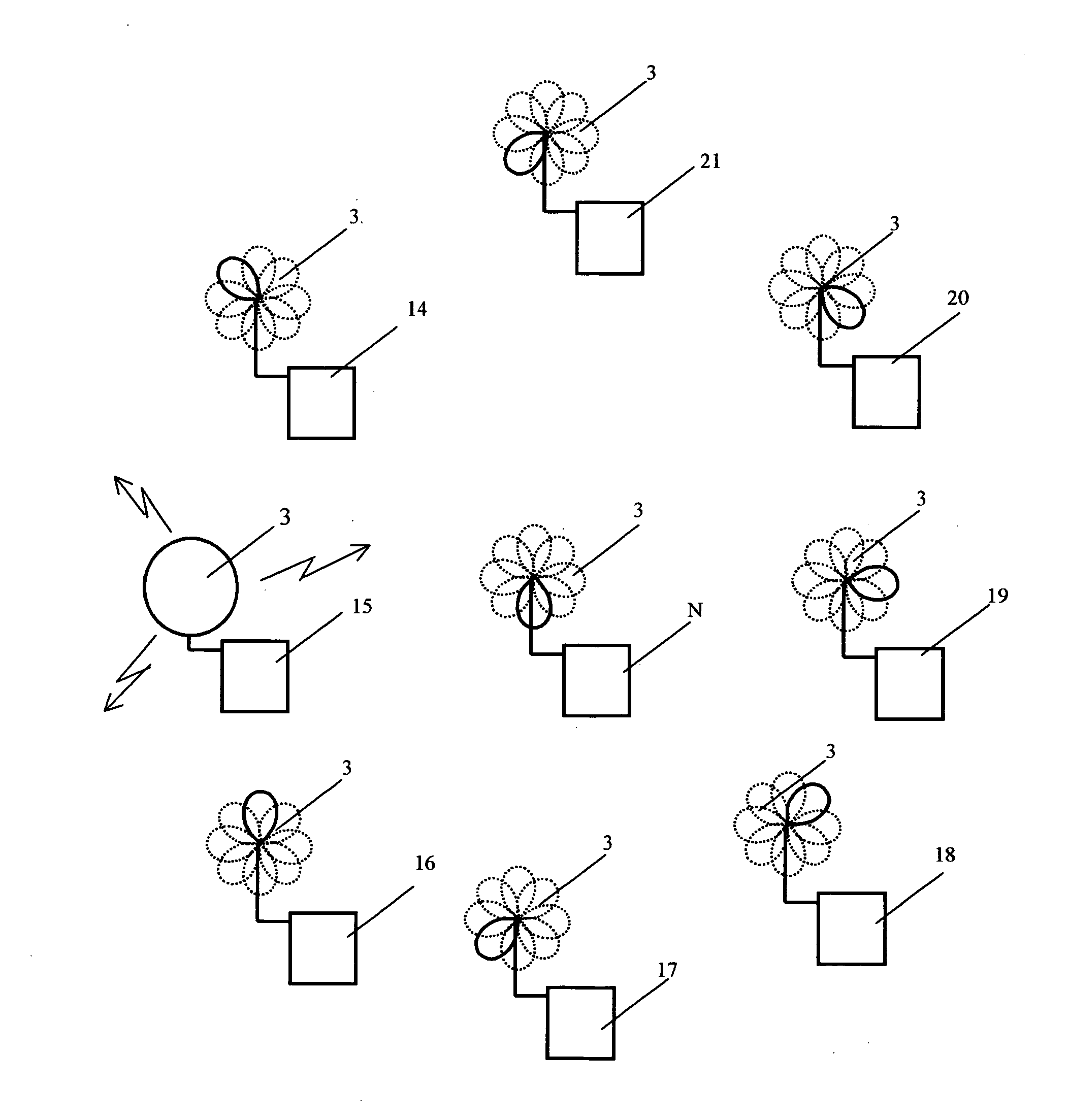
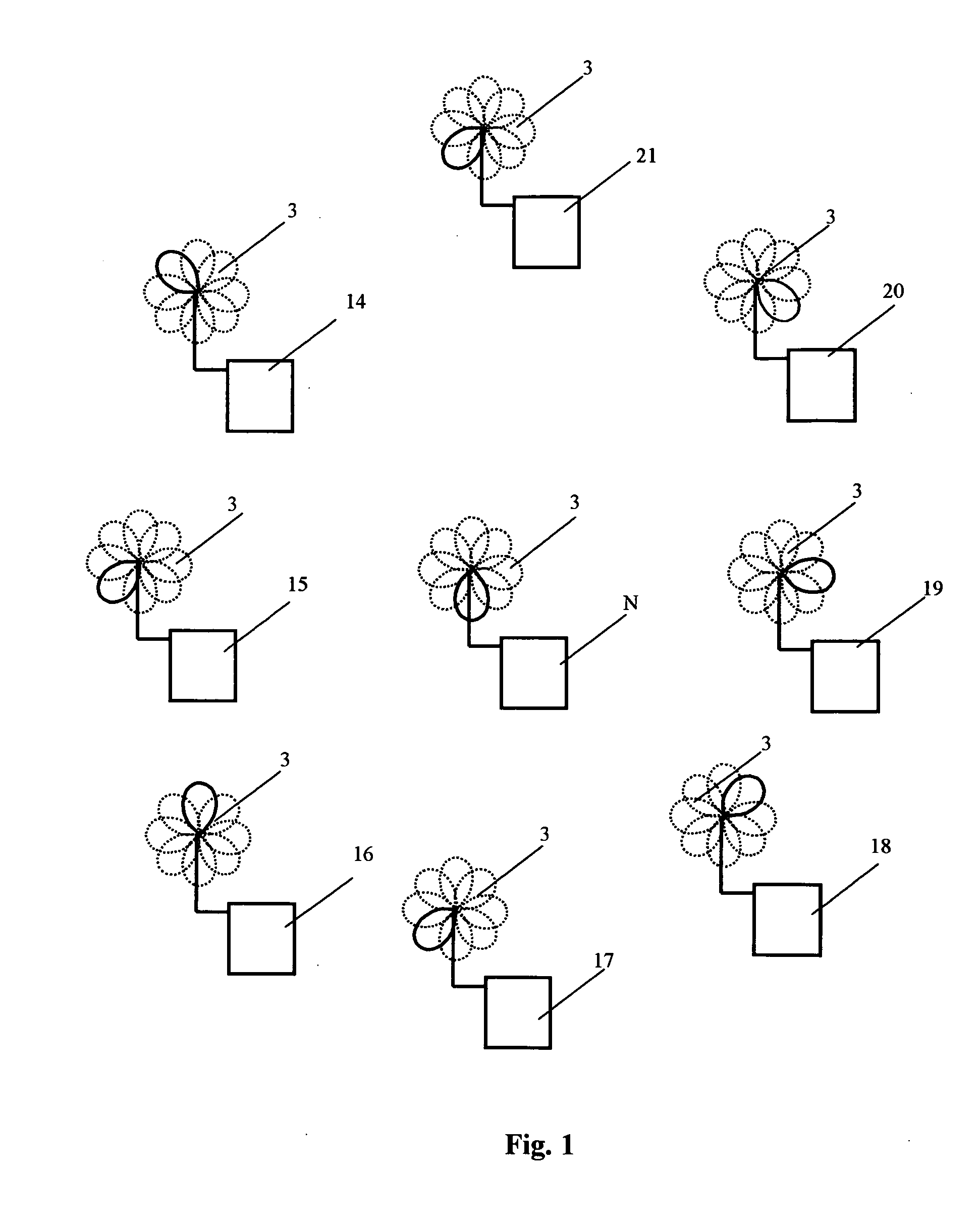
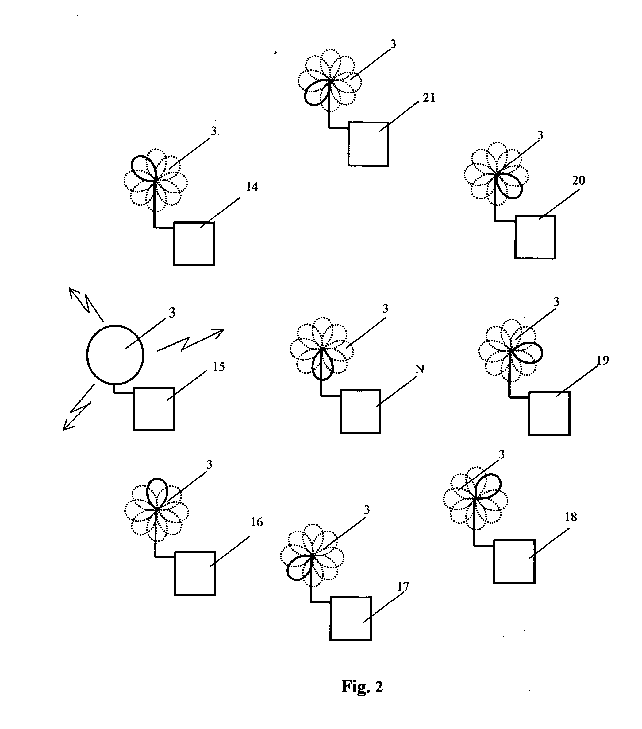
The method for radio communication in a WLAN can be implemented using the transceiving device, which is shown in FIG. 8 and FIG. 9 in the transmission and reception modes correspondingly. The transceiving device 1 comprises antenna unit 2 consisting of at least one directional antenna 3 featuring a directional pattern controlled by means of a directional pattern switchover unit 4. In terms of design, antenna unit 2 can be made in different ways—namely, in the form of one antenna 3 with at least two radiators with directional patterns that, taken together, cover no less than 360° by azimuth bearing or by the angle of elevation; in the form of one antenna 3 with at least three radiators (for example, with four or six radiators) with directional patterns that, taken together, cover the hemisphere or sphere by the azimuth bearing and by the angle of elevation. Antenna unit 2 can be also made with at least two said antennas 3, with each antenna having at least one radiator, the direction...


PUM


Abstract

Method for radio communication in a wireless local area network and transceiving device refers to wireless local area networks (WLAN) consisting of a multitude of transceiving devices of users (14, 15, 16 . . . N). Implies simultaneous scanning by their antenna beams in different directions by transceiving devices (with said transceiving devices being in reception mode) and transmission of an omnidirectional signal in the form of calibration signal and data package by one of the transceiving devices of said network (with said transceiving device being in transmission mode), reception of the signal by transceiving devices operating in reception mode and subsequent orientation of their antenna beams in the direction of signal source. Said recognition and orientation is performed during the period of reception of said calibration signal. The Method increases the range of a WLAN, reduces the transmission time and improves quality and reliability of communication. Each transceiving device (1) includes at least one directional antenna (3) featuring a controllable directional pattern, switched-over by unit (4), reception/transmission mode switch (5), receiver (8), transmitter (10) and controller (11). Additionally a unit for signal detection (13) is incorporated in the device.

Description

FIELD OF THE INVENTIONThe invention claimed herein refers to wireless local communication networks (WLAN), namely, to methods and equipment used in said networks for the purpose of transmission / reception of various types of information.BACKGROUND OF THE INVENTIONCurrently wireless local communication networks are finding more and more extensive use in the field of information science and videographic communication for the purpose of transmission and distribution of data / information among multiple users located inside the same building (for example, among personal computers, laptop computers, printers and other users located in the same building without any restrictions on the “mobility” of these devices). Transmission of information with the use of WLAN allows one to reduce cost because there is no necessity of laying connecting wires. A network of this type could be also used in those cases when it is either difficult or impossible to lay connecting wires and in cases when there ar...

Claims


Application Information

Patent Timeline
IPC IPC(8): H04W84/12H04B7/00H01Q1/24H01Q3/24H01Q3/26H01Q21/20H01Q25/00H04B7/06H04L12/28H04L12/56
CPCH01Q1/246H01Q3/242H01Q3/267H01Q21/205H04W84/12H04B7/0602H04W16/28H04W24/00H01Q25/002
Inventor ABRAMOV, OLEG YURIEVICHKIRDIN, ALEKSANDR NIKOLAEVICHSUKHARNIKOV, YURY PAVLOVICH
Owner AIRGAIN INC
Why Eureka
Try Eureka