Hand-held power tool

a hand-held power tool and power technology, applied in the field can solve the problems of increasing size, reducing the operating cost of hand-held power tools, and reducing the operating cost of hand-held power tools, and achieving the effect of reliable and precise mode setting position over a comparatively long operating period

Active Publication Date: 2013-12-19
ROBERT BOSCH GMBH
View PDF2 Cites 19 Cited by
  • Summary
  • Abstract
  • Description
  • Claims
  • Application Information

AI Technical Summary

Benefits of technology

[0004]Therefore, an object of the present invention is to provide a new hand-held power tool for operation in hammer-drilling, drillin

Problems solved by technology

A disadvantage of the related art is that there is normally a predetermined axial free space between the transmission element and the mode-setting sleeve, which may increase in size over the service life o

Method used


Image

  • Hand-held power tool
  • Hand-held power tool
  • Hand-held power tool

Examples


Embodiment Construction

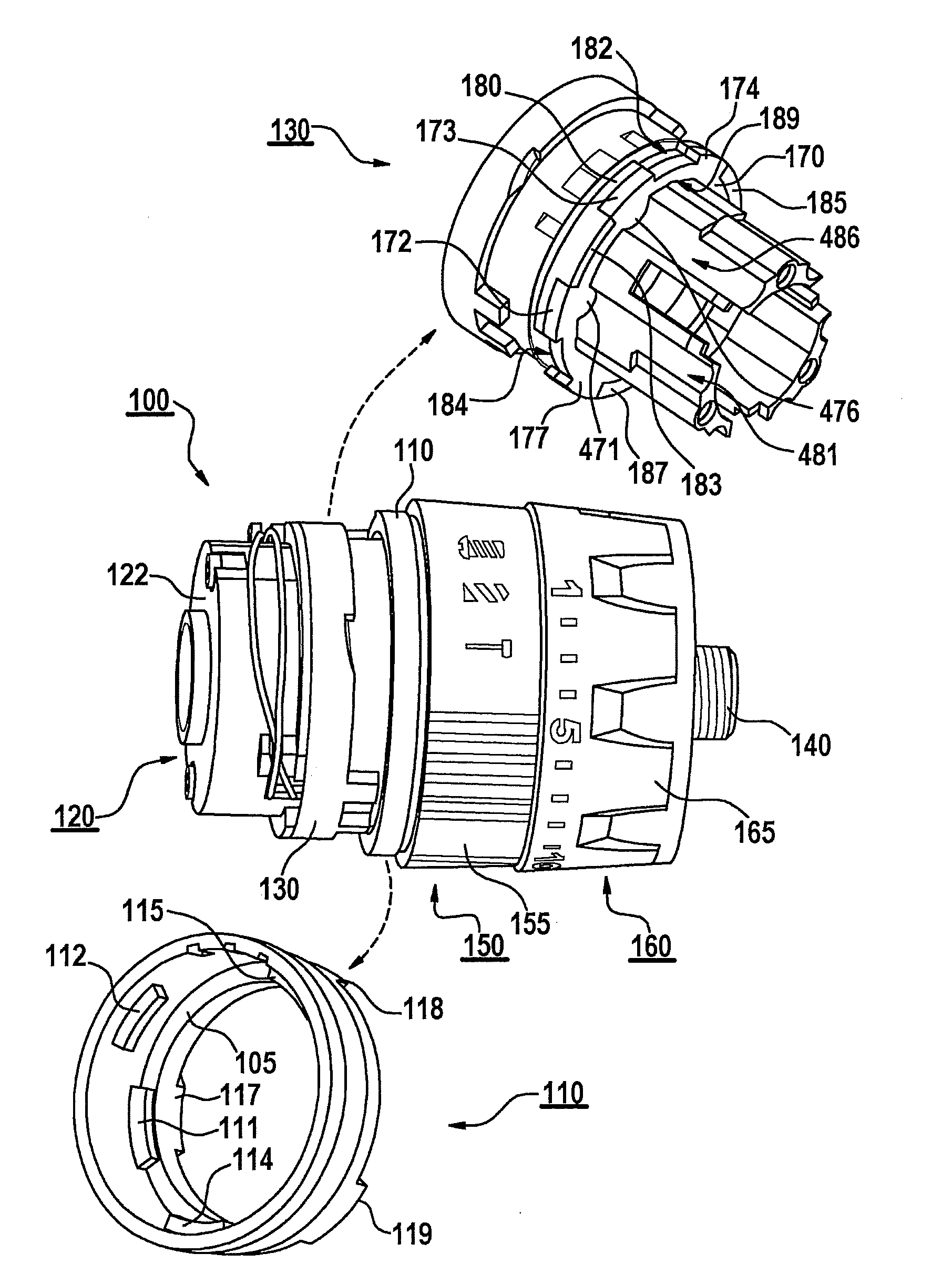
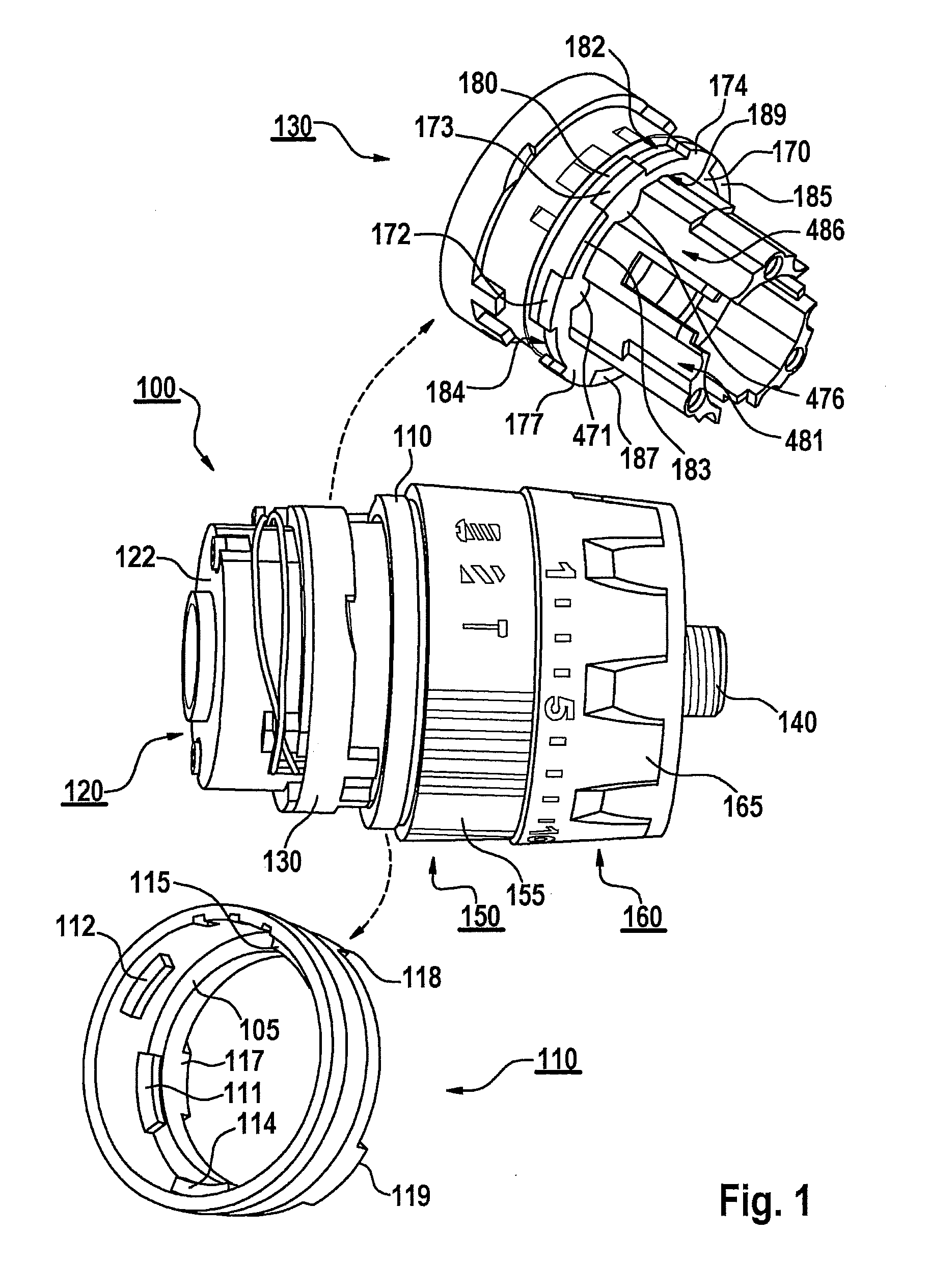
[0042]FIG. 1 shows a hand-held power tool 100 for operation in hammer-drilling, drilling and screwing modes in accordance with the present invention. To simplify the drawing, hand-held power tool 100 is only illustrated sectionally, in light of a gear unit 120, a mode-setting device 150 having a setting element 110, a torque-setting device 160, as well as an output shaft 140.

[0043]According to one specific embodiment, hand-held power tool 100 has a driving device, e.g., an electric drive motor, for driving gear unit 120. An angular motion of the drive motor is transmitted to output shaft 140, which is illustratively formed in the manner of a tool spindle, and to which, e.g., a chuck may be attached for receiving an insertable tool. Gear unit 120 is situated, for example, in a gear housing 122, which is connected to a coupling housing 130 and may form coupling housing 130 at least in sections.

[0044]For purposes of illustration, coupling housing 130 is formed in the shape of a sleeve ...


PUM


Abstract

A hand-held power tool having hammer-drilling, drilling and screwing modes, including a mode-setting device having an actuating element, a setting element, and a gear unit for driving an output shaft, in which the actuating and setting elements are interconnected in a rotatably fixed manner, and, in an operating mode(s), the setting element is coupled to a transmission element supported at a coupling housing assigned to the gear unit and axially displaceable at the coupling housing in a screwing position associated with the screwing mode and is axially fixed in position at the coupling housing in hammer-drilling and drilling positions of the corresponding modes; the transmission element is connected to the coupling housing in a rotatably fixed manner, a predefined operating mode being settable by rotating the setting element; the setting and transmission elements being rotatable relative to one another, the setting element embracing at least sections of the transmission element.

Description

FIELD OF THE INVENTION[0001]The present invention relates to a hand-held power tool for operation in hammer-drilling, drilling and screwing modes, which includes a mode-setting device having an actuating element and a setting element, as well as a gear unit for driving an output shaft; the actuating element and the setting element being interconnected in a rotatably fixed manner, and, at least in one operating mode, the setting element being coupled to a transmission element, which is supported at a coupling housing assigned to the gear unit and, in a screwing position associated with the screwing mode, is axially displaceable at the coupling housing and, in hammer-drilling and drilling positions associated with the hammer-drilling and drilling modes, is axially fixed at the coupling housing.BACKGROUND INFORMATION[0002]Such a hand-held power tool, which includes a driving device provided for driving an output shaft that has a drive unit and a gear unit coupled to the drive unit, is ...

Claims


Application Information

Patent Timeline
IPC IPC(8): B25D16/00
CPCB25D16/006B25B23/141B25D2211/064B25D2216/0023B25D2216/0038B25D2216/0092B25D2250/165
Inventor HECHT, JOACHIMROEHM, HEIKOKRAUS, MARTIN
Owner ROBERT BOSCH GMBH
Why Eureka
Try Eureka