Liquid Vessel Pourer with Timed Illuminator for Measuring Purposes

a technology of timed illumination and pourer, which is applied in the direction of electric winding, instruments, horology, etc., can solve the problems of not using a counter means that is activated by gravity switch, known and disclosed devices, etc., and achieves convenient fabrication, not wasteful expenditure, and preserves the battery life of the unit

Active Publication Date: 2013-12-19
HOUCK NICK +1
View PDF26 Cites 30 Cited by
  • Summary
  • Abstract
  • Description
  • Claims
  • Application Information

AI Technical Summary

Benefits of technology

[0016]In view of the foregoing disadvantages inherent in the known types of liquid pourers now present in the prior art, the present invention provides a new, illuminated liquid pourer that can be utilized for providing convenience for the user when dispensing a specified amount of liquor from a liquor bottle using a flashing light source as a counter for measurement purposes.
[0020]Yet another object of the present invention is to provide a new and improved liquid bottle pourer that has a sealed internal structure and internal circuitry, wherein the overall pourer is constructed to allow for a reasonable replacement cost of the device such that disposal after the battery has been drained is efficient and not a wasteful expenditure.
[0021]Another object of the present invention is to provide a new and improved liquid bottle pourer that includes a battery switch for preserving battery life of the unit between uses and during shipment of the pourer prior to use.
[0022]A final object of the present invention is to provide a new and improved liquor bottle pourer that may be readily fabricated from materials that permit relative economy and that are commensurate with durability.

Problems solved by technology

Similar to Buker, the Escobar device is designed for ornamental purposes, and does not utilize a means of detecting the quantity of liquor being dispensed through the bottle pourer.
The devices known and disclosed in the prior art, however, do not utilize a counter means that is activated by a gravity switch.

Method used


Image

  • Liquid Vessel Pourer with Timed Illuminator for Measuring Purposes
  • Liquid Vessel Pourer with Timed Illuminator for Measuring Purposes
  • Liquid Vessel Pourer with Timed Illuminator for Measuring Purposes

Examples


Embodiment Construction

[0033]Reference is made herein to the attached drawings. Like reference numerals are used throughout the drawings to depict like or similar elements of the liquid bottle pourer. For the purposes of presenting a brief and clear description of the present invention, the preferred embodiment will be discussed as used for measuring a quantity of fluid poured from a liquid bottle using a visual indicator. The figures are intended for representative purposes only and should not be considered to be limiting in any respect.

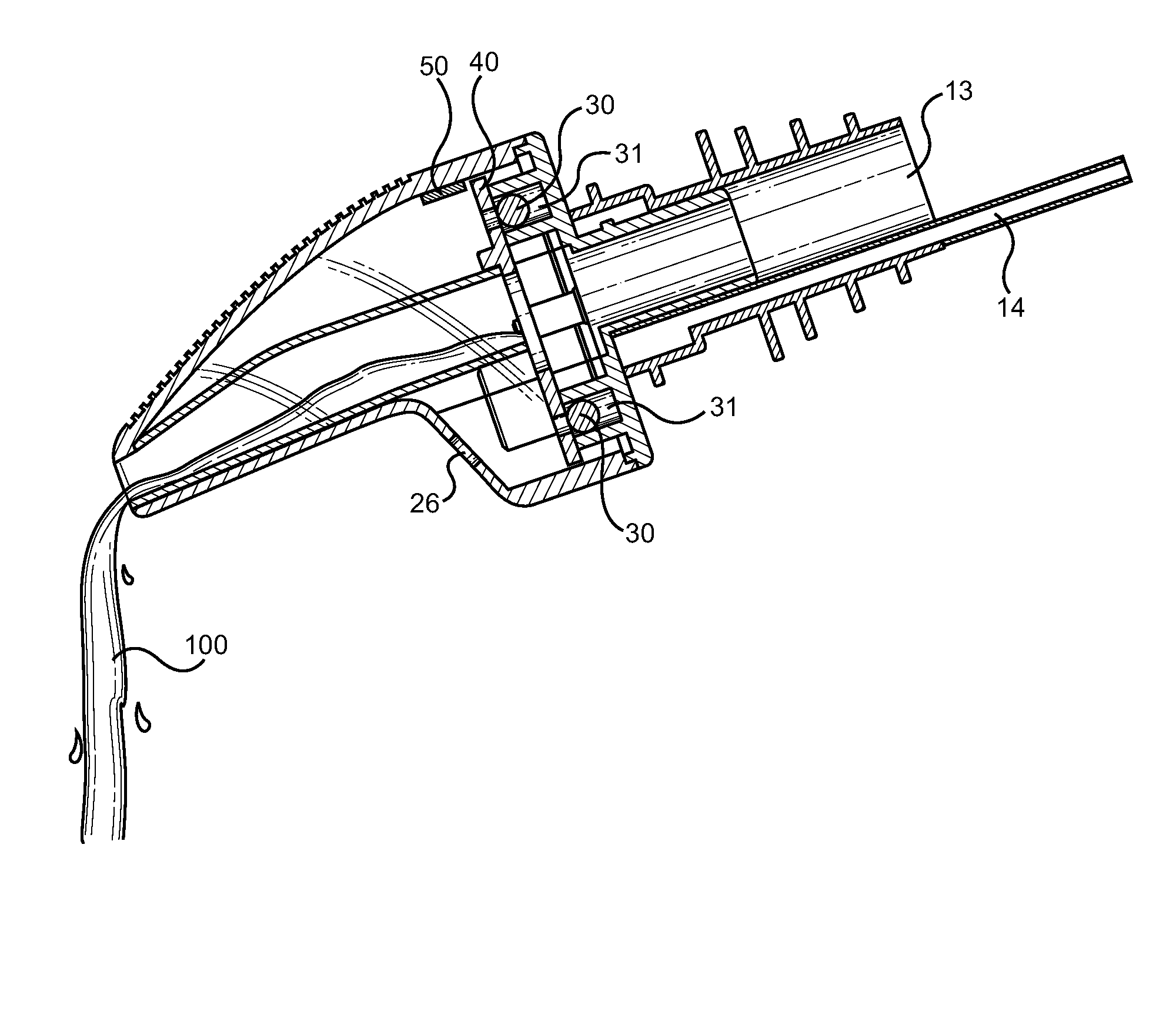
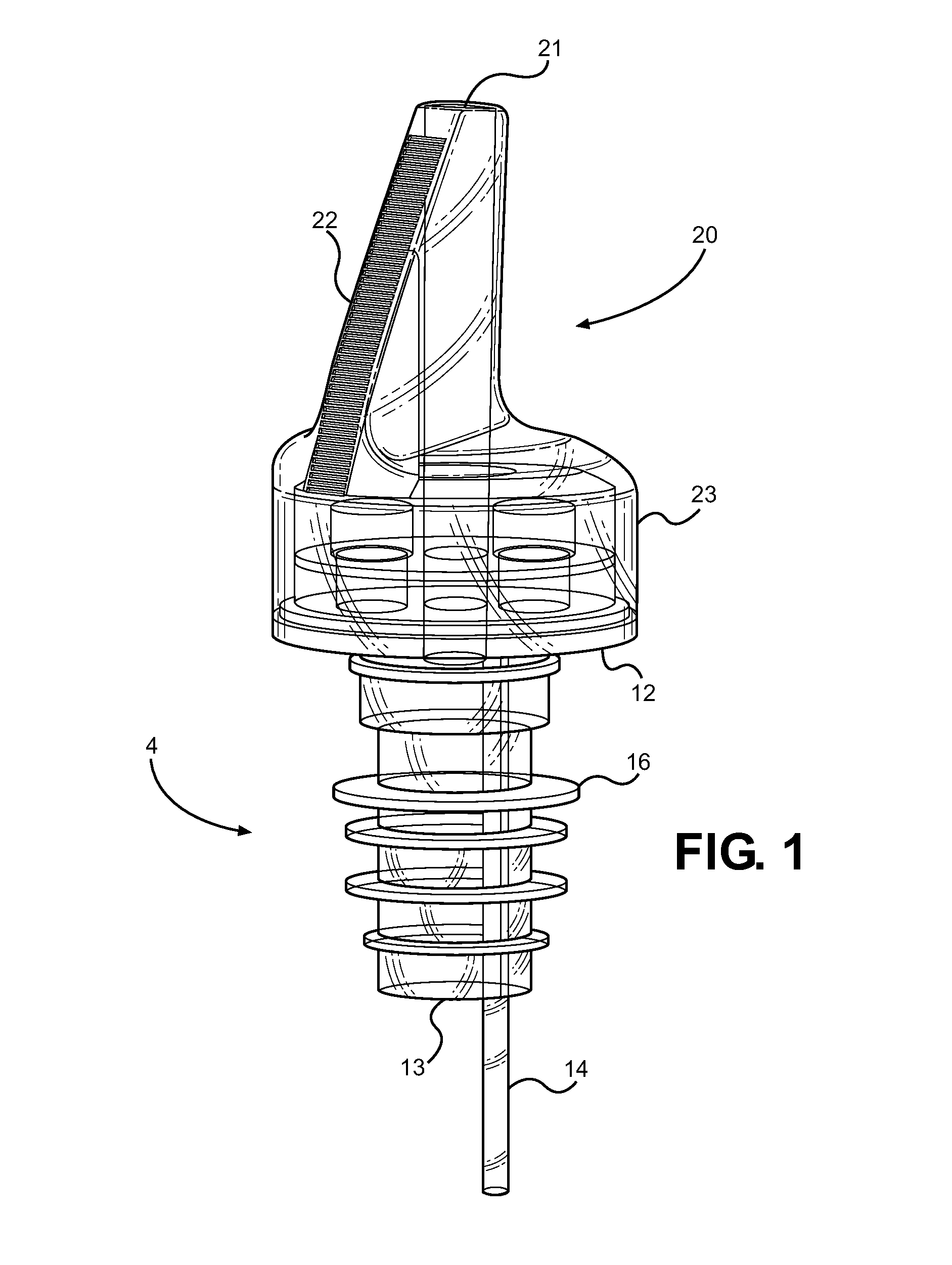
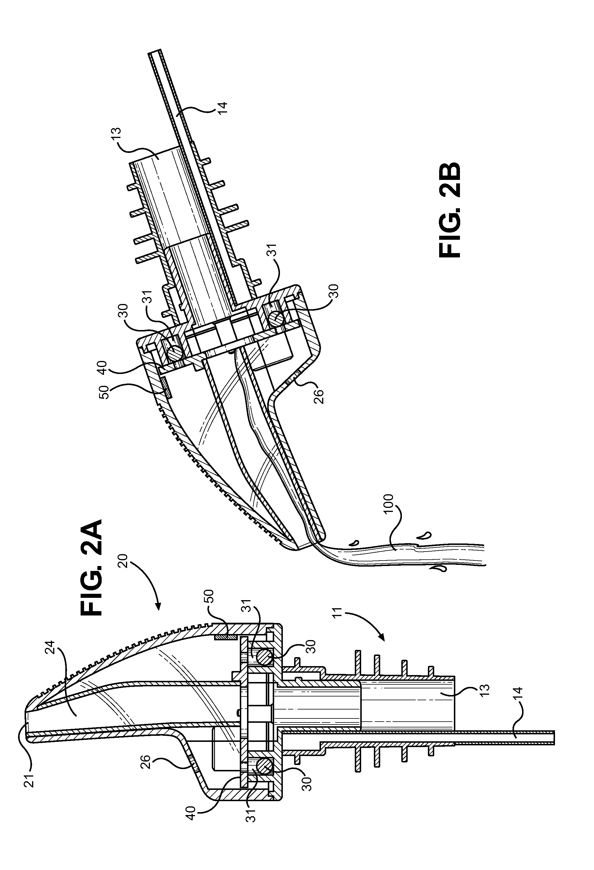
[0034]Referring now to FIG. 1, there is shown a perspective view of an exemplary embodiment of the pourer device of the present invention. The device comprises a largely standard pourer structure, wherein the device includes a pour spout upper 20 and a liquid conduit lower portion 11 that is adapted to be positioned within a bottle open upper. The device includes a base 12 that forms a seal over a container opening, an air relief tube 14 extending through the base 12, a p...


PUM


Abstract

An illuminating bottle pourer is provided having a pour spout structure and internal electrical components for measuring the amount of dispensed fluid therethrough using a visual counter. The device includes a gravity contact switch and an LED light source that is energized based on a periodic timer circuit and a pulse generator circuit. The gravity switch is closed when the bottle is inverted for pouring, which initiates the timer circuit. The timer circuit triggers the pulse generator on a periodic basis, which energizes the light source to alert the pourer of a given quantity of fluid dispensed. The device allows individual drink makers, bartenders, and establishment owners to precisely control the amount of fluid being dispensed from a bottle, wherein a specified number of light pulses is used to indicate when to stop pouring. A battery switch is further provided to preserve battery life during shipment and between uses.

Description

CROSS REFERENCE TO RELATED APPLICATION[0001]This application claims the benefit of U.S. Provisional Application No. 61 / 661,587 filed on Jun. 19, 2012, entitled “Pour Assist.” The above identified patent application is herein incorporated by reference in its entirety to provide continuity of disclosure.BACKGROUND OF THE INVENTION[0002]1. Field of the Invention[0003]The present invention relates to a fluid dispenser. More specifically, the present invention pertains to a liquor bottle pourer having an illumination means that acts as a visual counter for measuring a predefined quantity of liquid poured from an attached bottle.[0004]Making mixed drinks, including alcoholic and non-alcoholic beverages, requires careful measurement of each ingredient to ensure the proper mixture is created and one ingredient does not overpower another. This makes pouring the correct amount of a particular fluid extremely important for proper drink mixing, cooking, baking, and other activities. The implica...

Claims


Application Information

Patent Timeline
Patent Type & Authority Applications(United States)
IPC IPC(8): B67D7/06G04C1/12B65D5/66
CPCB67D3/0041B67D3/0077G01F13/006H01H1/16H01H35/02
Inventor HOUCK, NICKLOPICCOLO, MARCO
Owner HOUCK NICK
Why Eureka
Try Eureka