Eletromagnetic opening/closing device

a technology of electromagnetic opening and closing device, applied in the direction of electromagnetic relay details, magnetic/electric field switch, contact testing/inspection, etc., can solve the problem of impaired contact conductivity between contacts (a stationary contact and a moving contact)

Active Publication Date: 2013-12-19
PANASONIC INTELLECTUAL PROPERTY MANAGEMENT CO LTD
View PDF10 Cites 39 Cited by
  • Summary
  • Abstract
  • Description
  • Claims
  • Application Information

AI Technical Summary

Benefits of technology

[0013]The electromagnetic opening / closing device of the present invention can perform self-checking on the presence or absence of malfunction to give a notification to the exterior.

Problems solved by technology

In such electromagnetic opening / closing devices, the conduction between contacts (a stationary contact and a moving contact) may be impaired due to surface oxidation thereof, or the stationary contact and the moving contact may be welded to each other due to arc.

Method used


Image

  • Eletromagnetic opening/closing device
  • Eletromagnetic opening/closing device
  • Eletromagnetic opening/closing device

Examples


embodiment 1

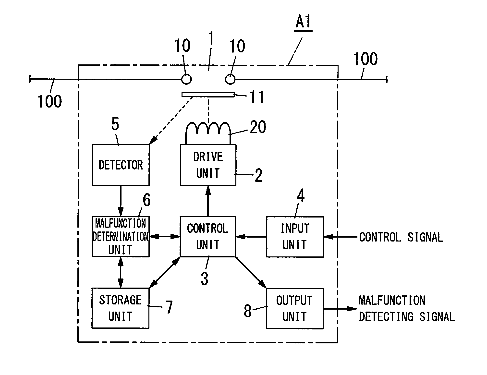
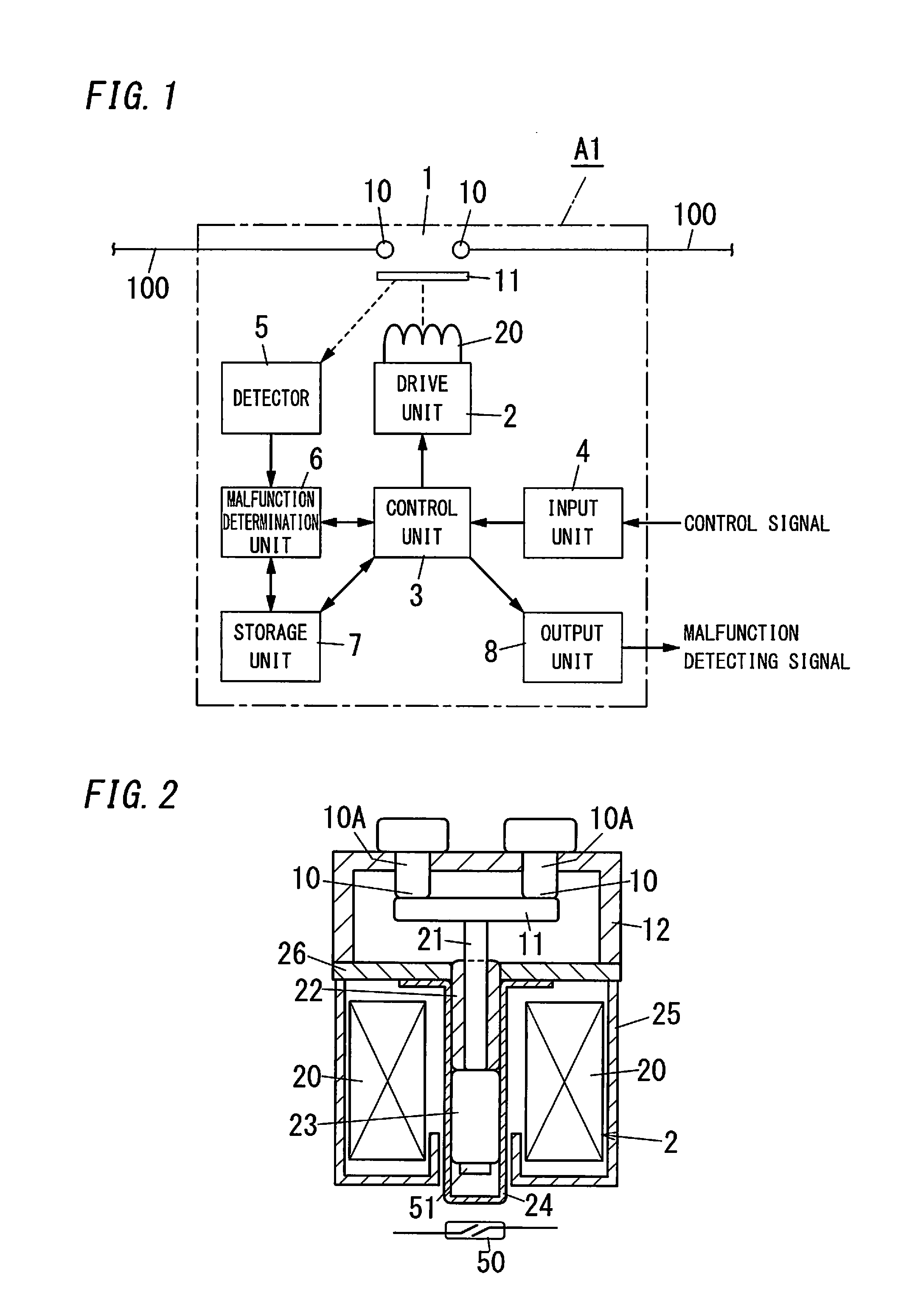
[0029]FIG. 1 shows an electromagnetic opening / closing device A1 in accordance with an embodiment 1 of the present invention. The electromagnetic opening / closing device A1 includes at least one stationary contact 10 and a moving contact 11, and is configured to open or close the stationary contact 10 and the moving contact 11 in accordance with an exterior command for opening or closing the stationary contact 10 and the moving contact 11. In the example of FIG. 1, the electromagnetic opening / closing device A1 includes a contact unit 1, a drive unit 2, a control unit 3, an input unit 4, a detector 5, a malfunction determination unit 6, a storage unit 7, an output unit 8 and the like. The contact unit 1 has two stationary contacts 10 inserted along an electrical circuit 100 and a moving contact (a mover) 11 configured to come into contact with or separate from the stationary contacts 10. That is, the contact unit 1 is closed and the electrical circuit 100 is in a conducting state when ...

embodiment 2

[0047]An electromagnetic opening / closing device A2 in the present embodiment has the same fundamental construction as embodiment 1, hence like kind elements are assigned the same reference numerals as depicted in embodiment 1, and illustrations and description of the configuration are omitted.

[0048]As shown in FIGS. 9A and 9B, a detector 5 in the present embodiment includes a detection coil 53 placed at a position facing an end face (a lower end) of a cap 24, and is configured to detect an opened or closed state of a contact unit 1 by a characteristic, of an electric circuit including the detection coil 53, varying in response to a distance between the coil and a movable core 23.

[0049]The detector 5 has, for example, an LC oscillator circuit formed of a parallel circuit of the detection coil 53 and a capacitor (not shown). When the movable core 23 made of metal approaches the detection coil 53 of the LC oscillator circuit, an eddy-current loss caused by electromagnetic induction occ...

embodiment 3

[0054]An electromagnetic opening / closing device A3 in the present embodiment has the same fundamental construction as embodiment 1, hence like kind elements are assigned the same reference numerals as depicted in embodiment 1, and illustrations and description of the configuration are omitted.

[0055]A detector 5 in the present embodiment is configured to detect a movement of a movable core 23 through a magnetic sensor 55 with a Hall effect sensor. For example, as shown in FIG. 12 A, the magnetic sensor 55 is placed at a second side of a first direction with respect to an end face of a cap 24 (at a lower position than the end face of the cap 24), and detects a position of a permanent magnet 51 attached on an end face (a lower face) of the movable core 23. In another example, the magnetic sensor 55 is placed at a lateral side of the cap 24 as shown in FIG. 12B. In this example, the permanent magnet 51 is attached on a tip end (a lower end) of a support member 52 placed on a bottom of t...


PUM


Abstract

An electromagnetic opening/closing device A1 includes a detector 5 for detecting an opened or closed state of a contact unit 1; a malfunction determination unit 6 configured to determine presence or absence of malfunction based on the opened or closed state of the contact unit 1 detected through the detector 5 and an opened or closed state of the contact unit 1 corresponding to an exterior command; and an output unit 8 configured to supply an exterior with a determination result by the malfunction determination unit 6.

Description

TECHNICAL FIELD [0001]The invention relates to an electromagnetic opening / closing device such as an electromagnetic relay or the like.BACKGROUND ART[0002]For example, Japanese Patent Application Publication No. 2009-230921 (hereafter called “Document 1”) discloses an electromagnetic opening / closing device as a prior art. In the device described in Document 1, a relay unit (an electromagnetic relay) is put in a case made from synthetic resin, and a pair of main terminals and a pair of coil terminals are protruded from the case. The pair of main terminals is connected to contacts of the relay unit, and the pair of coil terminals is connected to a coil for an electromagnet of the relay unit. In addition, the pair of main terminals is connected to a power supply line from a power supply to a load(s). The relay unit (the electromagnetic opening / closing device) is turned on when an excitation current flows between the pair of coil terminals, while the relay unit (the device) is turned off...

Claims


Application Information

Patent Timeline
Patent Type & Authority Applications(United States)
IPC IPC(8): H01H47/00
CPCH01H47/002H01H1/0015H01H9/0066H01H36/0046H01H50/541H01H50/545
Inventor KODAMA, KAZUHIROOKADA, TAKESHI
Owner PANASONIC INTELLECTUAL PROPERTY MANAGEMENT CO LTD
Why Eureka
Try Eureka