Battery pack with high structural reliability

a battery pack and high structural reliability technology, applied in battery/cell propulsion, cell components, electrochemical generators, etc., can solve the problems of air pollution, need to secure sufficient rigidity of the lower plate, and difficulty in preventing vibration, impact or the lik

Active Publication Date: 2013-12-26
LG ENERGY SOLUTION LTD
View PDF31 Cites 3 Cited by
  • Summary
  • Abstract
  • Description
  • Claims
  • Application Information

AI Technical Summary

Benefits of technology

[0013]It is an object of the present invention to provide a battery pack that is configured such that unit modules are mounted upwardly and fixed at the upper side in a state in which the unit modules are erected in an upside-down fashion when the battery pack is installed in a vehicle, such that external impact transferred to the battery pack can be significantly reduced by a moment of force.
[0042]In another example, the opposite ends of the rear mounting member may be bent parallel to the second upper mounting member and fastening holes may be formed at the bent portions of the rear mounting member to achieve easy coupling to the external device.

Problems solved by technology

One of the biggest problems caused by vehicles using fossil fuel such as gasoline and diesel is the creation of air pollution.
However, this structure has a problem in that there is a need to secure sufficient rigidity of the lower plate.
However, the above battery pack structured such that the unit modules 10 are fixed on the lower plate 20 has a problem in that it is difficult to prevent vibration, impact or the like from being transferred to the battery pack in an environment in which the vehicle often suddenly starts and suddenly stops.

Method used


Image

  • Battery pack with high structural reliability
  • Battery pack with high structural reliability
  • Battery pack with high structural reliability

Examples


Embodiment Construction

[0055]Now, embodiments of the present invention will be described in detail with reference to the accompanying drawings. However, it should be noted that the description of the embodiments is given to provide better understanding of the present invention without limiting the scope of the invention.

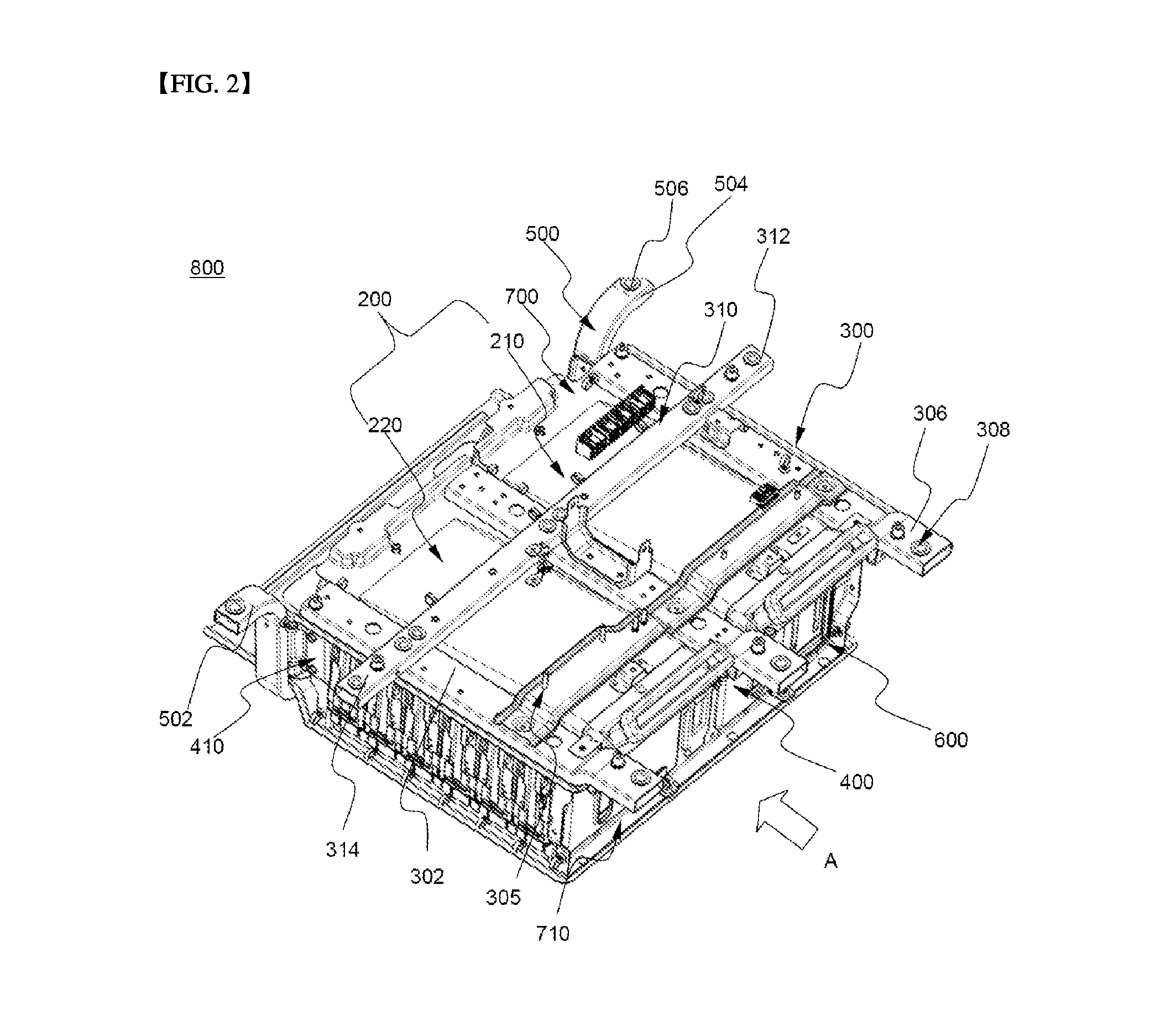
[0056]FIG. 2 is a schematic perspective view of a battery pack according to an embodiment of the present invention and FIG. 3 is a schematic rear perspective view of the battery pack of FIG. 2.

[0057]FIG. 4 is a schematic side perspective view of the battery pack of FIG. 2 and FIG. 5 is a schematic top perspective view of the battery pack of FIG. 2.

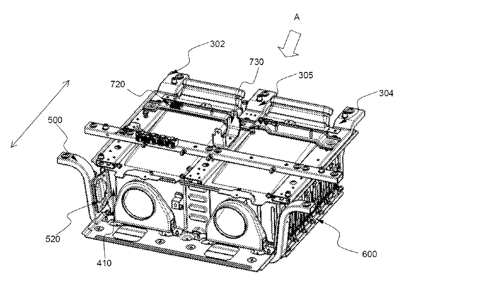
[0058]As shown in FIGS. 2 to 5, a battery pack 800 includes a battery module array 200, a pair of side support members (i.e., a front support member 400 and a rear support member 410), a lower end support member 600, three first upper mounting members 300, a second upper mounting member 310 and a rear mounting member 500.

[0059]The battery module ...


PUM

PropertyMeasurementUnit
weightaaaaaaaaaa
anglesaaaaaaaaaa
shapeaaaaaaaaaa

Abstract

Disclosed is a battery pack including a battery module array having battery modules arranged in two or more rows in a state in which the battery modules are erected in an upside-down fashion, each of the battery modules being formed by stacking battery cells or unit modules, each having two or more battery cells mounted therein, in a lateral direction with respect to electrode terminals of the battery cells, a front support member and a rear support member that are a pair of side support members to support the front and rear of the battery module array, respectively, lower end support members coupled to lower ends of the side support members, and mounting members coupled to an upper end of the battery module array and fastened to an external device such that an upper part of the battery pack is mounted to the external device.

Description

TECHNICAL FIELD[0001]The present invention relates to a battery pack with high structural reliability and, more particularly, to a battery pack including a battery module array having battery modules arranged in two or more rows in a state in which the battery modules are erected in an upside-down fashion, each of the battery modules being formed by stacking battery cells or unit modules, each having two or more battery cells mounted therein, in a lateral direction with respect to electrode terminals of the battery cells, a front support member and a rear support member that are a pair of side support members to support the front and rear of the battery module array, respectively, in a state in which the pair of side support members are in close contact with outermost unit modules in the battery modules in the battery module array, lower end support members coupled to lower ends of the side support members to support a lower end of the battery module array, and mounting members coup...

Claims


Application Information

Patent Timeline
Patent Type & Authority Applications(United States)
IPC IPC(8): H01M10/50B60K1/04H01M2/10H01M50/209
CPCH01M10/5016H01M2/1077B60K1/04H01M10/0525H01M50/209B60L50/66B60L50/60Y02E60/10Y02T10/70H01M50/249H01M50/124H01M50/103B60K2001/0416
Inventor LEE, BUMHYUNSHIN, YONG SHIKLEE, JIN KYUYOON, JONG MOONCHOO, YEONSEOK
Owner LG ENERGY SOLUTION LTD
Why Eureka
Try Eureka