Wireless chip and manufacturing method of the same
a technology of wireless chips and manufacturing methods, applied in the direction of electrical equipment, semiconductor devices, semiconductor/solid-state device details, etc., can solve the problems of complex fixation of wireless chips that have been used recently to a product, and achieve the effects of preventing degradation of thin film integrated circuits, reducing external impacts to a thin film integrated circuit, and easy washing
- Summary
- Abstract
- Description
- Claims
- Application Information
AI Technical Summary
Benefits of technology
Problems solved by technology
Method used
Image
Examples
embodiment 1
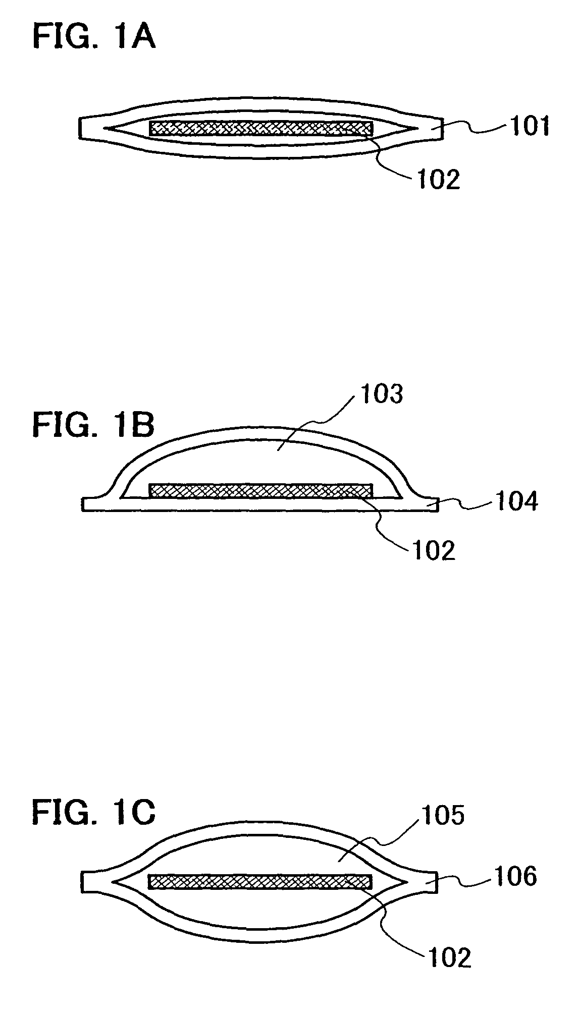
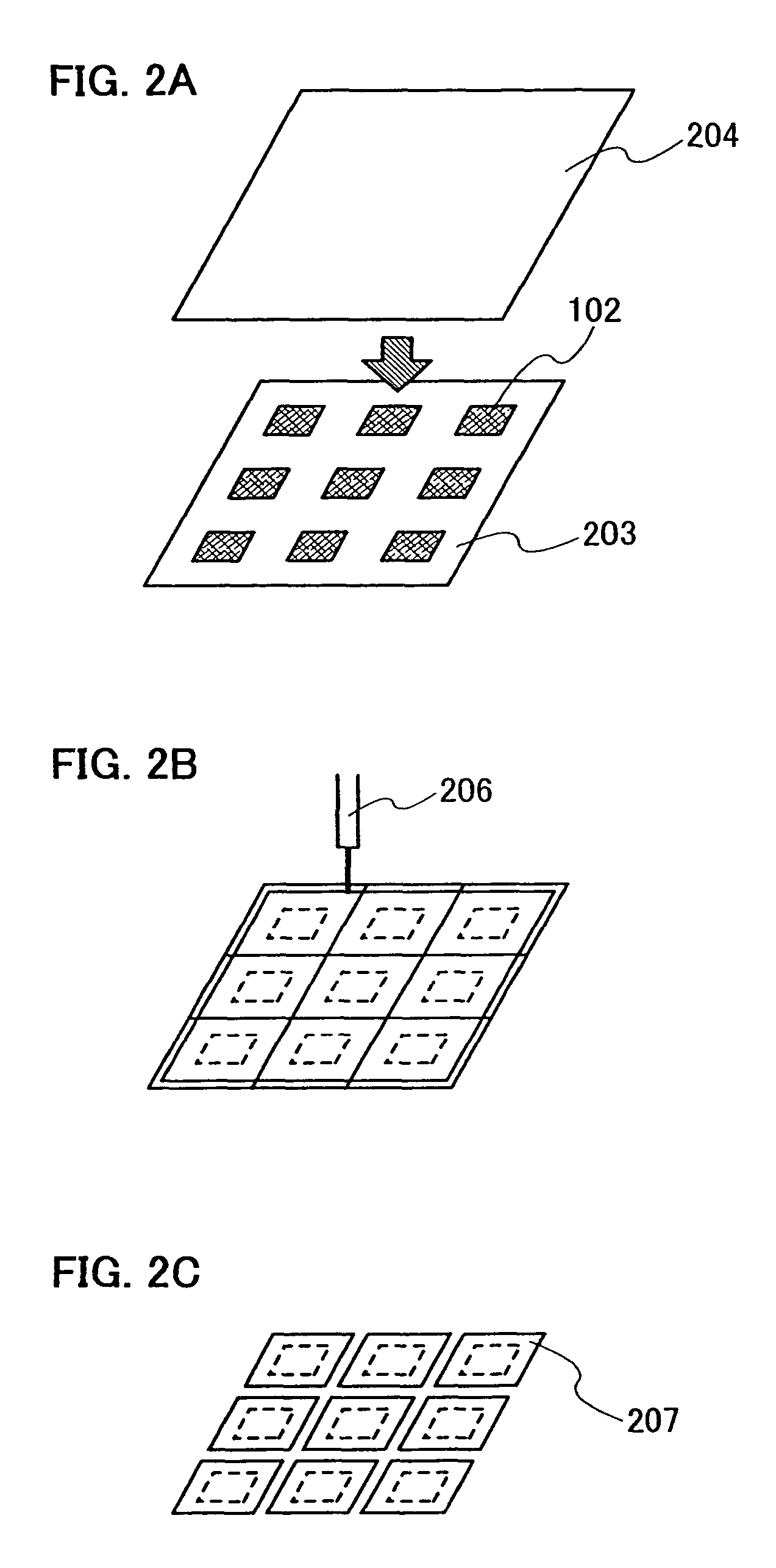
[0086]In Embodiment 1, an embodiment of a process up to arranging regularly a plurality of thin film integrated circuits 102 over the first film 203 is described.
[0087]First, a substrate 400 is prepared and a release layer 401 is formed over the substrate 400 as shown in FIG. 4A. Here, a release layer means a layer for facilitating releasing the plurality of thin film integrated circuits 102 from the substrate 400. Specifically, a glass substrate of, for example, barium borosilicate glass, aluminoborosilicate glass, a quartz substrate, a ceramic substrate, or the like can be used as the substrate 400. Further, a metal substrate such as stainless steel or a semiconductor substrate provided with an insulating film on its surface may also be used. Although a substrate made of a flexible plastic generally tends to have lower heat-resistance than the above-described substrate, it can be used as the substrate 400 as long as it can withstand process temperature in the manufacturing process...
embodiment 2
[0108]In Embodiment 2, a method of using a film having an adhesive agent on one side thereof when the thin film integrated circuits 408 on the substrate 400 are transferred onto the first film 203 as shown in Embodiment 1, is described with reference to FIGS. 14A to 14C.
[0109]A state in FIG. 4E or 5 is obtained according to the method shown in Embodiment 1. Then, the thin film integrated circuits 408 are bonded to a film 407 as shown in FIG. 14A by positioning the film 407 having an adhesive layer 406 on one side of a base 405 over the thin film integrated circuit 408 so that the adhesive layer 406 can be in contact with the thin film integrated circuit 408, and pressing them from above the thin film integrated circuit 408. FIG. 14A shows an example of bonding the thin film integrated circuits 408 to the film 407 in the state of FIG. 5.
[0110]The film 407 may have, specifically, a structure in which the adhesive layer 406 is provided on the base 405 formed of polyester, or the like. ...
embodiment 3
[0116]Embodiment 3 describes a process up to a state in which a plurality of thin film integrated circuits are arranged over the first film 203 as shown in FIG. 2A, which is different from that in Embodiment 1.
[0117]A layer 901 including a plurality of thin film integrated circuits (hereinafter, a TFT layer 901) is formed over one surface of a substrate 900 having an insulating surface (FIG. 9A). The substrate 900 corresponds to a glass substrate such as barium borosilicate glass or alumino borosilicate glass, a quartz substrate, a ceramic substrate, a plastic substrate, an acrylic substrate, or the like. A metal substrate such as stainless steel or a semiconductor substrate having an insulating layer on its surface may also be used. The substrate 900 can be easily manufactured to have a length of 1 m or more on a side, and can have a desired shape such as a square or circular shape. Therefore, when the substrate 900 has a size of 1 m or more on a side, for example, the productivity...
PUM
 Abstract
Description
Claims
Application Information
 - R&D
- Intellectual Property
- Life Sciences
- Materials
- Tech Scout
- Unparalleled Data Quality
- Higher Quality Content
- 60% Fewer Hallucinations
Browse by: Latest US Patents, China's latest patents, Technical Efficacy Thesaurus, Application Domain, Technology Topic, Popular Technical Reports.
© 2025 PatSnap. All rights reserved.Legal|Privacy policy|Modern Slavery Act Transparency Statement|Sitemap|About US| Contact US: help@patsnap.com


