
Receptacle cleaning systems and methods for the same

a technology for cleaning systems and receptacles, applied in the field of receptacle cleaning, can solve the problems of prone to bending, difficult cleaning access, and debris in the female receptacle,

Active Publication Date: 2014-01-02
RAYTHEON CO
View PDF10 Cites 3 Cited by
  • Summary
  • Abstract
  • Description
  • Claims
  • Application Information

AI Technical Summary

Benefits of technology

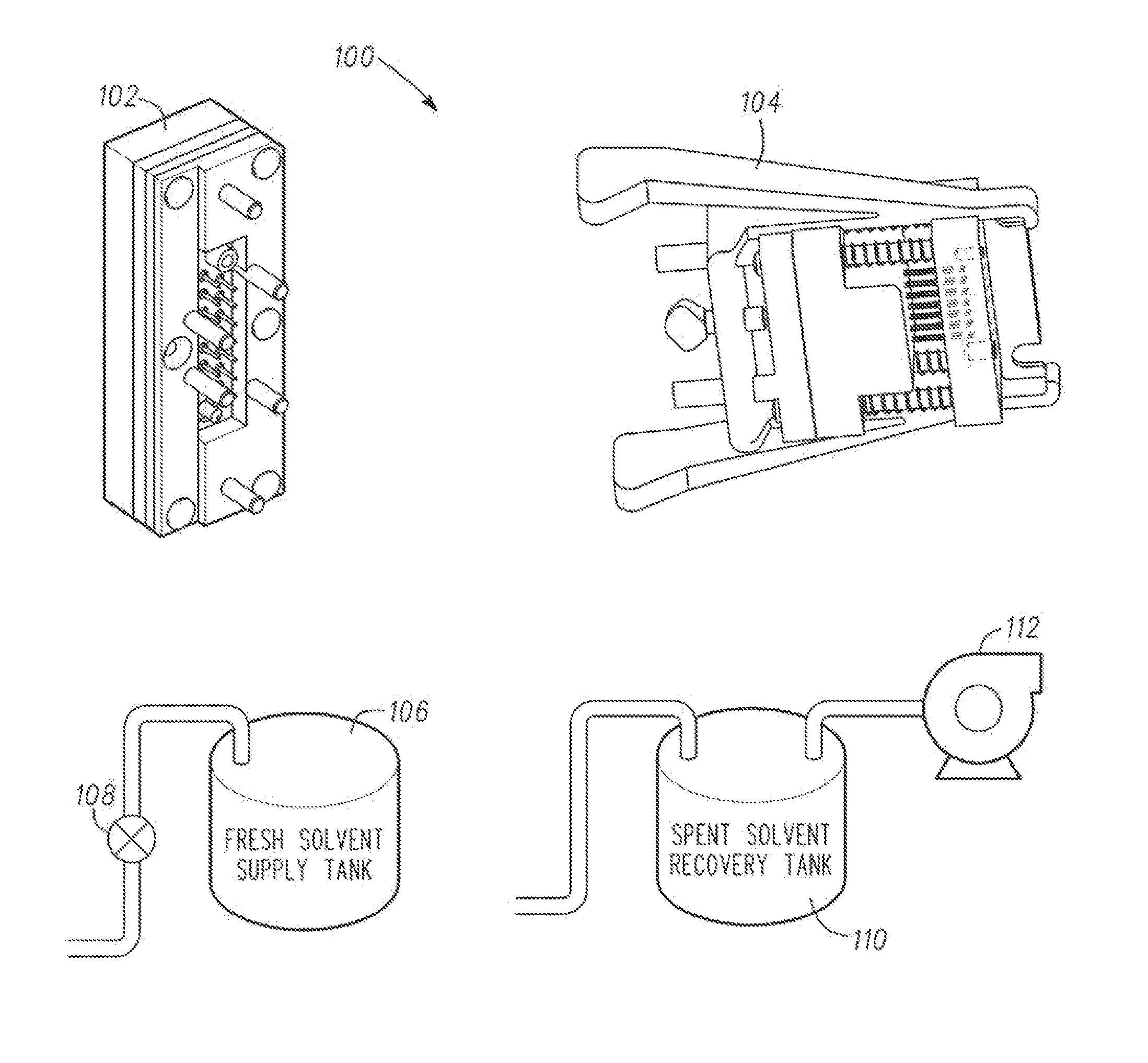
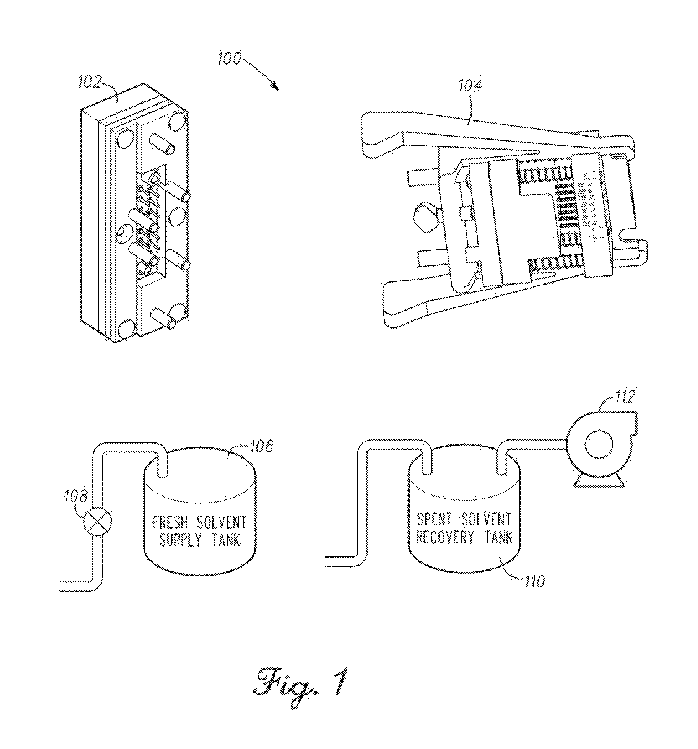
The patent text describes a solution for cleaning receptacles used in electrical and data cabling. The problem being addressed is the buildup of debris on the contacts of connectors, which can be difficult to reach without exposing sensitive components to cleaning solutions. The invention provides a receptacle cleaning assembly that includes a receptacle washing fixture and a receptacle brush fixture. The receptacle washing fixture has multiple nozzles that provide a flow of cleaning solution into each of the receptacle sockets, while the receptacle brush fixture has a pattern of reciprocating brushes that mechanically abrade debris and remove it through reciprocation. The invention allows for cleaning the receptacle while it is installed, ensuring each socket is cleaned.

Problems solved by technology

During one or more of assembly, use, storage, maintenance and the like the female receptacles may become fouled with debris, dirt, solder flux and the like.
The female receptacles are often small, for instance with a diameter of less than 0.125 inches, have a large length relative to the diameter, and correspondingly provide a difficult to access location for cleaning.
The small width brush shafts are smaller than the receptacles and are prone to bending when improperly inserted in the female receptacles.
In another case, debris at the openings is instead funneled and pushed into the receptacles thereby frustrating further attempts at removal.
With a connector installed in a piece of equipment it is difficult to reach the connector and clean the connector without also exposing surrounding sensitive components to cleaning solutions, such as solvents.

Method used


Image

  • Receptacle cleaning systems and methods for the same
  • Receptacle cleaning systems and methods for the same
  • Receptacle cleaning systems and methods for the same

Examples


example 1

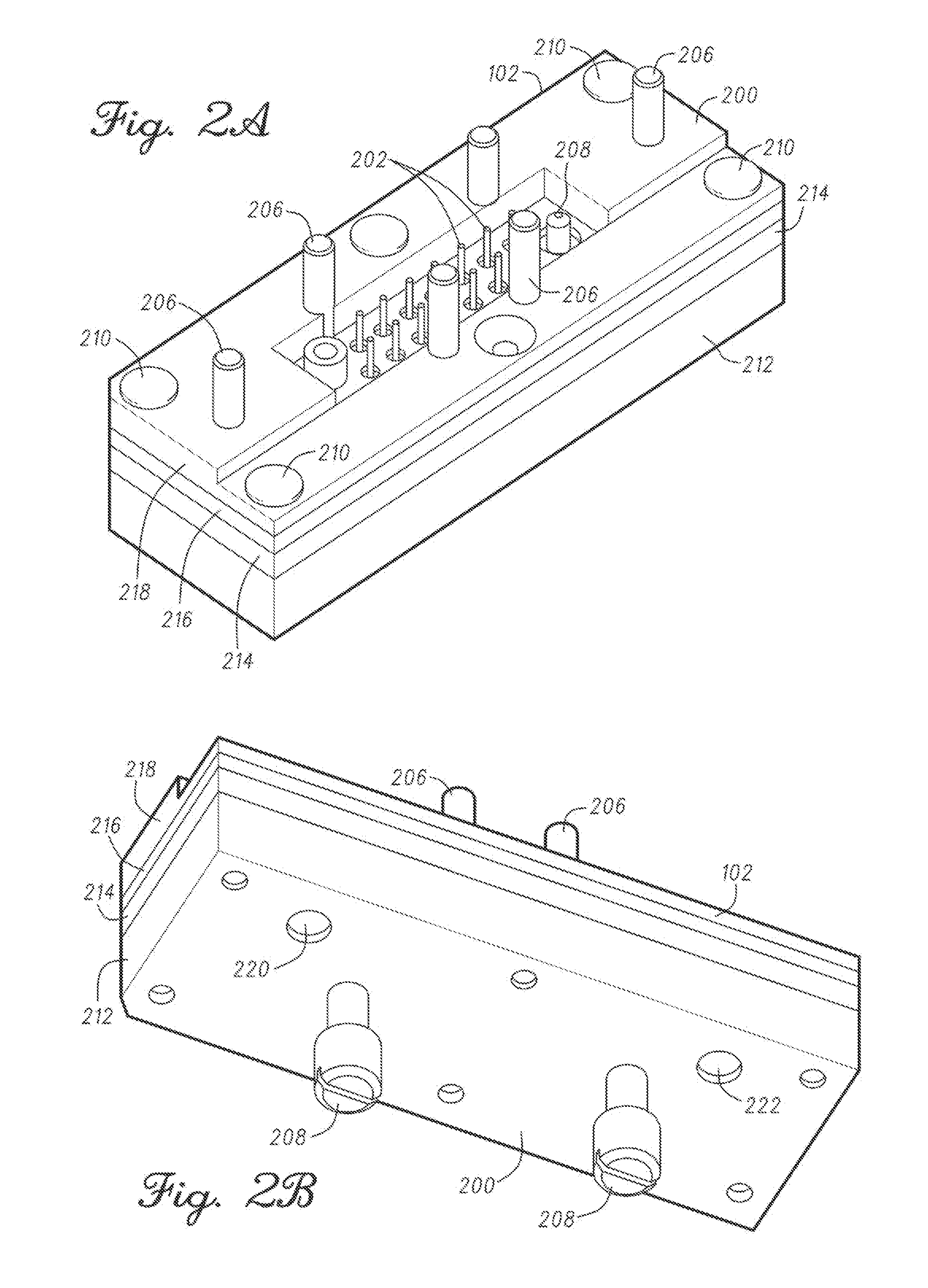
[0089 can include subject matter, such as an apparatus, that can include a receptacle cleaning assembly comprising a receptacle washing fixture including a manifold body including a solution inlet and a solution outlet: a plurality of nozzles coupled with the manifold body and arranged in a pattern corresponding to a pattern of female receptacles of a connector, the plurality of nozzles are in communication with the solution inlet; an interface seal coupled with the manifold body, the plurality of nozzles extend through the interface seal, the interface seal is configured to seal along a face of the connector, at least one solution return passage extending through the interface seal from an exterior of the plurality of nozzles to the solution outlet; and an alignment skirt extending from the manifold body, the alignment skirt is sized and shaped to couple with the connector and align the plurality of nozzles with the female receptacles.

[0090]Example 2 can include, or can optionally ...


PUM


Abstract

A receptacle cleaning assembly for use with electrical connectors includes a receptacle washing fixture having a manifold body with a solution inlet and outlet. A plurality of nozzles, in communication with the solution inlet, are coupled with the manifold body and are arranged in a pattern corresponding to female connector receptacles. An interface seal is coupled with the manifold body. The plurality of nozzles extend through the interface seal, and the interface seal is configured to seal along a face of the connector. At least one solution return passage extends through the interface seal from an exterior of the plurality of nozzles to the solution outlet. An alignment skirt extends from the manifold body, and couples and aligns the connector receptacles with the plurality of nozzles. In another example, the receptacle cleaning assembly includes a receptacle brush fixture including a plurality of reciprocating brushes for use in the female connector receptacles.

Description

STATEMENT REGARDING FEDERALLY SPONSORED RESEARCH OR DEVELOPMENT[0001]This invention was made with government support under award number W31P4Q-06-C-0466. The government has certain rights in this invention.COPYRIGHT NOTICE[0002]A portion of the disclosure of this patent document contains material that is subject to copyright protection. The copyright owner has no objection to the facsimile reproduction by anyone of the patent document or the patent disclosure, as it appears in the Patent and Trademark Office patent files or records, but otherwise reserves all copyright rights whatsoever. The following notice applies to the software and data as described below and in the drawings that form a part of this document: Copyright Raytheon Company; Waltham, Mass.; All Rights Reserved.TECHNICAL FIELD[0003]This document pertains generally, but not by way of limitation, to cleaning of receptacles used in electrical and data cabling.BACKGROUND[0004]Electrical connectors, such as connectors used...

Claims


Application Information

Patent Timeline
Patent Type & Authority Applications(United States)
IPC IPC(8): B08B9/08B08B9/087A46B13/04B08B9/093B08B3/00A47L7/00
CPCA46B11/06A46B2200/30A46B2200/3013B08B3/04B08B9/0323B08B2203/0229H01R43/002H01R43/14
Inventor MUSANTE, STEVEN A.
Owner RAYTHEON CO
Learn More