Damping Element for a Motor Vehicle Hydraulic System

a technology for hydraulic systems and motor vehicles, applied in mechanical equipment, braking systems, transportation and packaging, etc., can solve problems such as hydraulic fluid pulsation, rapid brake pressure build-up rates, and hydraulic pump operating capacity reduction

Active Publication Date: 2014-01-02
KELSEY HAYES CO +1
View PDF7 Cites 24 Cited by
  • Summary
  • Abstract
  • Description
  • Claims
  • Application Information

AI Technical Summary

Benefits of technology

[0011]In one embodiment, a motor vehicle hydraulic unit includes a hydraulic control unit (HCU) that includes a housing having bores for mounting valves and the like and channels for directing fluid. The damping element or attenuator may be mounted in one of the bores in the HCU. The damping element may be mounted in a fluid tight arrangement and may be retained, in part, by caulking. The HCU may be a vehicular hydraulic braking unit or a vehicular hydraulic steering unit.

Problems solved by technology

In this case, rapid brake pressure build-up rates may occur.
An issue related to the operation of hydraulic systems, generally, is that hydraulic fluid pulsations may occur due to the operation of a hydraulic pump or for other reasons.
These types of pulsations can lead to undesirable operating noises and can furthermore reduce the operating capacity of a hydraulic pump.

Method used


Image

  • Damping Element for a Motor Vehicle Hydraulic System
  • Damping Element for a Motor Vehicle Hydraulic System
  • Damping Element for a Motor Vehicle Hydraulic System

Examples


first embodiment

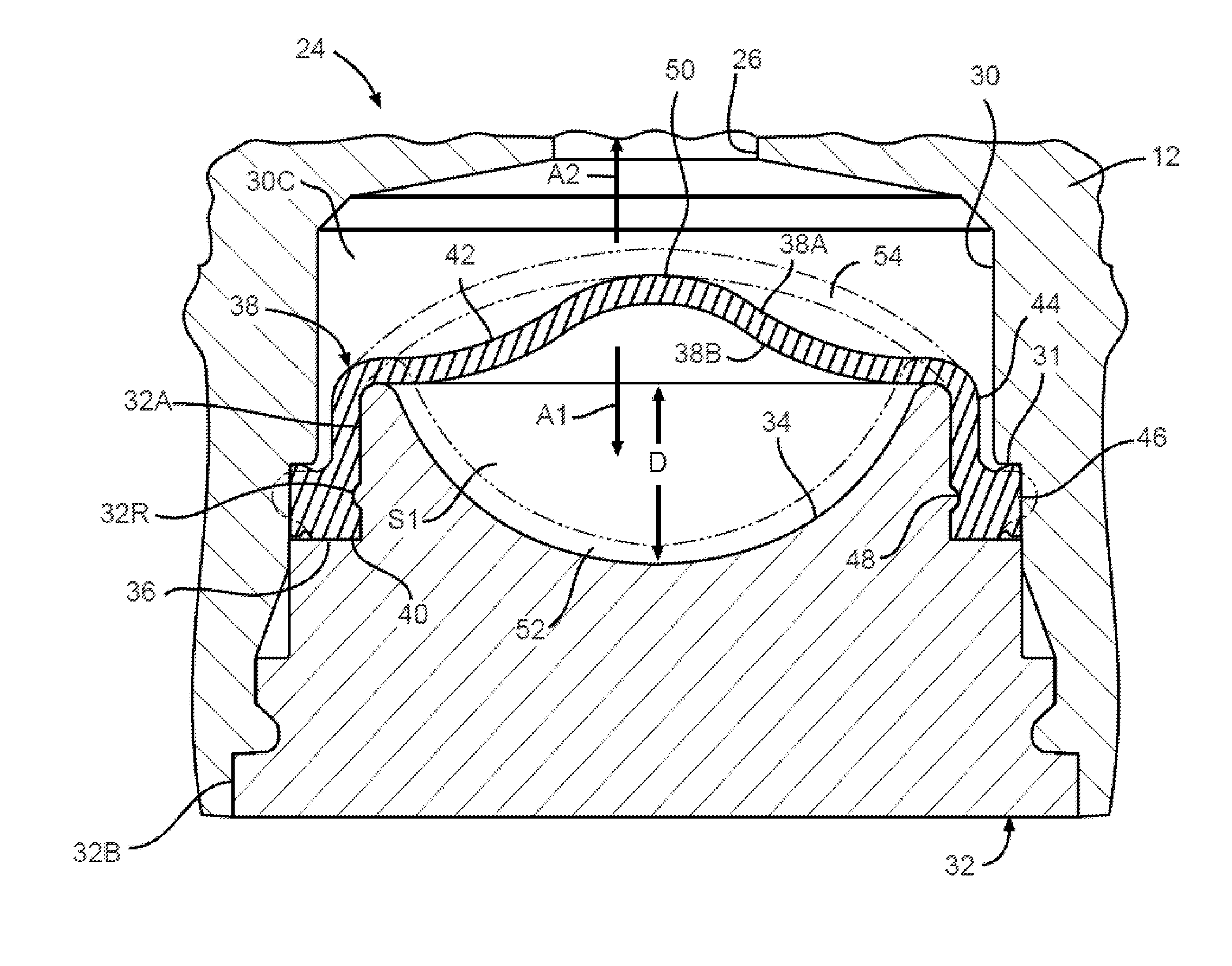
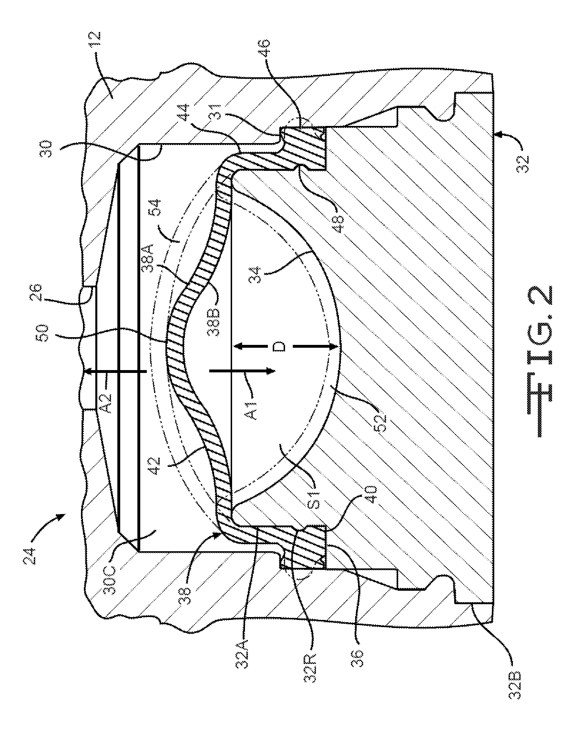
[0032]the attenuator 24 is illustrated in FIG. 2. In the illustrated embodiment, the attenuator 24 is disposed in the attenuator bore 30 of the valve housing 12. In the illustrated embodiment, the valve housing 12 is a hydraulic control unit (HCU). The bore 30 includes a stepped portion 31 which defines a seat for a sealing portion of a membrane 38, described below.

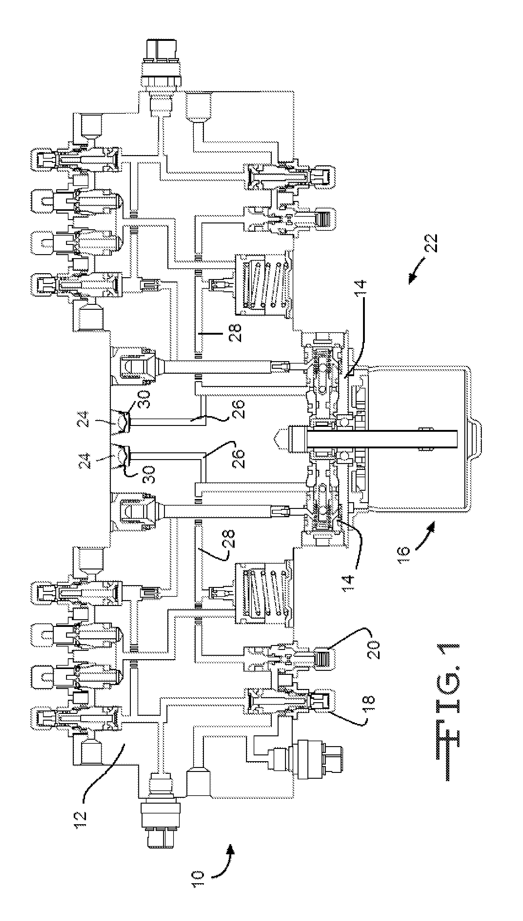
[0033]The fluid conduit 26 is formed in the HCU 12 and allows pressurized fluid flow between the pump 20 and the bore 30 via a pump fluid inlet conduit 28, shown in FIG. 1.

[0034]The attenuator 24 includes a support body, also known as an end cap 32, that is mounted in the bore 30 in a fluid-tight manner, such as by caulking, clinching, staking, press fitting, bonding, welding, or any other suitable method or combination of methods. The attenuator 24 may be permanently or removably mounted in the bore 30. The end cap 32 includes a first end 32A which faces the fluid conduit 26. A cavity 34, having a concave profile, is for...

second embodiment

[0038]Referring now to FIG. 3, a portion of the attenuator is shown at 124. The attenuator 124 is similar to the attenuator 24 and includes the end cap 32 and a membrane 138. The membrane 138 is similar to the membrane 38, is generally cup-shaped, and includes an open end 140, a closed end 142, and a substantially cylindrical side wall 144. A circumferentially outwardly extending sealing flange 146 is formed at the open end 140. A circumferentially outwardly extending groove 148 is formed on the inner surface of the side wall 144 opposite the flange 146. The closed end 142 has a substantially domed shape extending across the first end 32A of the end cap 32 and extending toward the conduit 26. As shown, the closed end 142 has a generally arcuate cross-sectional shape.

third embodiment

[0039]Referring now to FIG. 4, a portion of an attenuator is shown at 224. The attenuator 224 is similar to the attenuator 24 and includes an end cap 232 and a membrane 238. The end cap 232 includes a first end 232A which faces the fluid conduit 26. A concave cavity 234 is formed in the first end 32A of the end cap 232. The concave cavity 234 is configured as having a shallower depth than the depth D of the concave cavity 34, though such is not required. In the illustrated embodiment, the first end 232A of the end cap 232 has a diameter smaller than a diameter of a second end 232B of the end cap 232. A stepped portion 236 is formed between the first end 232A and the second end 232B of the end cap 232 and defines a seat for a sealing portion of the membrane 238. A circumferentially inwardly extending groove 232G is formed on the outer surface of the first end 232A of the end cap 232.

[0040]The membrane 238 is similar to the membrane 38, is substantially cup-shaped and includes an open...


PUM


Abstract

A damping element for attenuating hydraulic pressure pulses is integrated into a hydraulic chamber of a motor vehicle hydraulic system. The damping element includes a end cap support body and a membrane that fits over a portion of the support body. The membrane has a first side facing towards a source of hydraulic fluid and a second side facing away from the hydraulic fluid source. At least one space is provided between the second side of the membrane and the end cap support body to allow for deformation of the membrane under hydraulic pressure. The membrane has a collar with a lip seal provided for fitting into place on the wall of the hydraulic chamber. At least one second space for receiving hydraulic fluid is defined between the lip seal and a region of the membrane opposite the lip seal.

Description

CROSS-REFERENCE TO RELATED APPLICATIONS[0001]This application claims the benefit of German Patent Application No. 10 2012 012 971.8, filed Jun. 29, 2012, and U.S. Provisional Application No. 61 / 748,459, filed Jan. 3, 2013. The disclosures of both applications are incorporated herein by reference.BACKGROUND OF THE INVENTION[0002]This invention relates in general to motor vehicle hydraulic systems. In particular, this invention relates to a damping element for integration into a hydraulic system, such as a motor vehicle hydraulic system.[0003]Hydraulic systems are provided in various applications within a motor vehicle. Hydraulic brake and steering systems are two examples of such systems. These systems rely on hydraulic pressure, created by various sources, to effect their intended operation. Devices for autonomously generating brake pressure are part of driver assistance functions, such as, for example, a vehicle stability control (VSC). Autonomously generating brake pressure makes ...

Claims


Application Information

Patent Timeline
Patent Type & Authority Applications(United States)
IPC IPC(8): F15B1/04
CPCF15B1/04B60T17/04F16L55/053B60T8/368B60T8/4031B60T8/4068B62D5/0472F16L55/04
Inventor WALD, THOMASLOPEZ-LAREQUI, DAVIDKEDAK, GEORGZEOLI, JOSEPH F.STARR, JOSEPH A.CALDWELL, WILLIAM P.SWARICH, RICHARD A.
Owner KELSEY HAYES CO
Why Eureka
Try Eureka