
Pneumatic tire tread

Active Publication Date: 2014-01-09
MICHELIN & CO CIE GEN DES ESTAB MICHELIN
View PDF3 Cites 3 Cited by
  • Summary
  • Abstract
  • Description
  • Claims
  • Application Information

AI Technical Summary

Benefits of technology

The present invention aims to provide a pneumatic tire that can reduce the air column resonance sound and maintain drainage performance while allowing the groove fences to wear to a degree equivalent to the tread portion. This is achieved by utilizing a tread design that allows for equal wear between the groove fenses and tread portion, resulting in improved tire performance and reduced noise.

Problems solved by technology

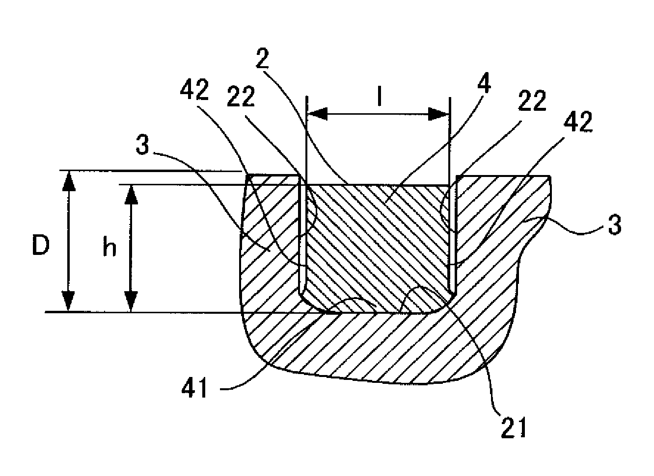
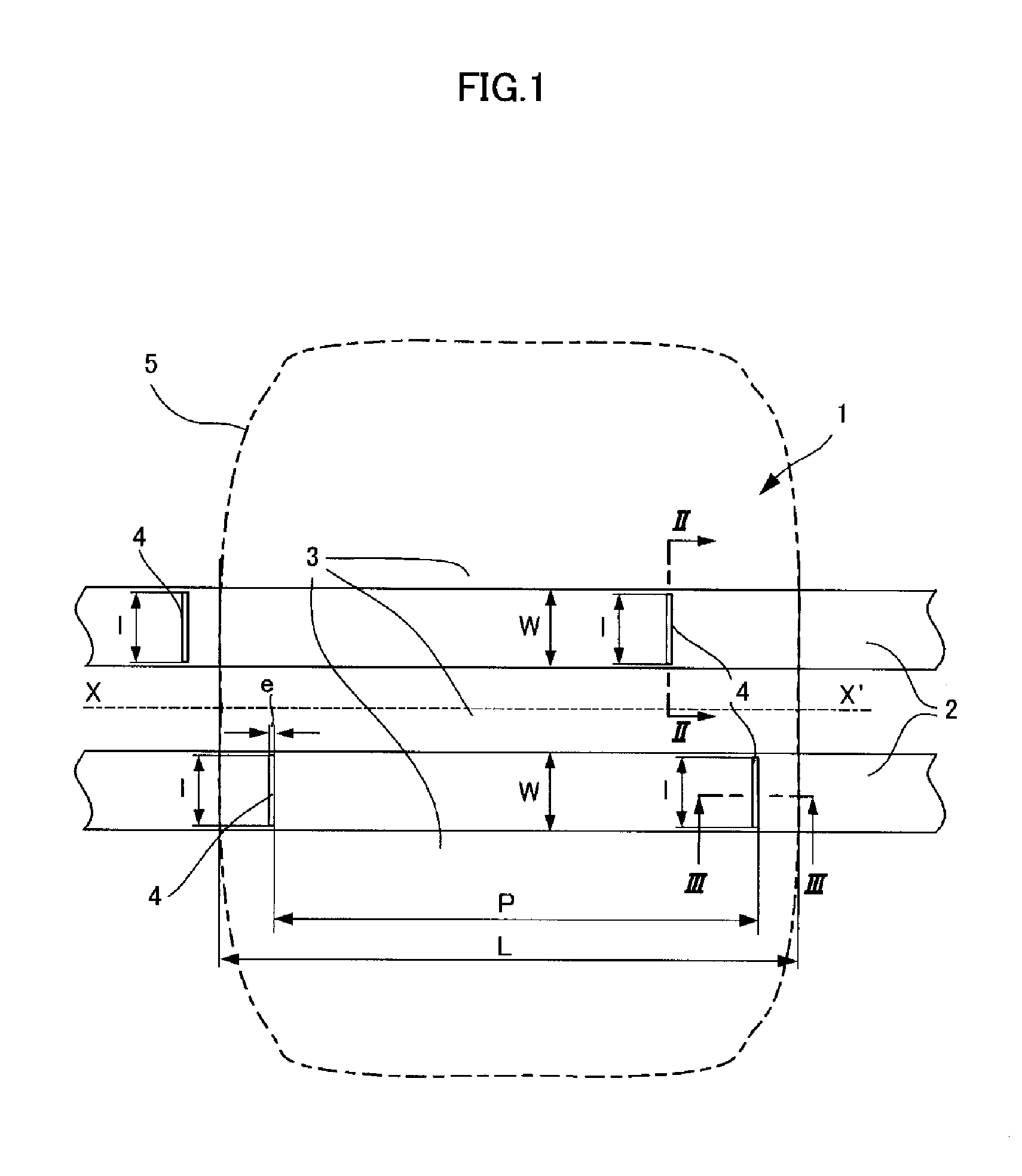
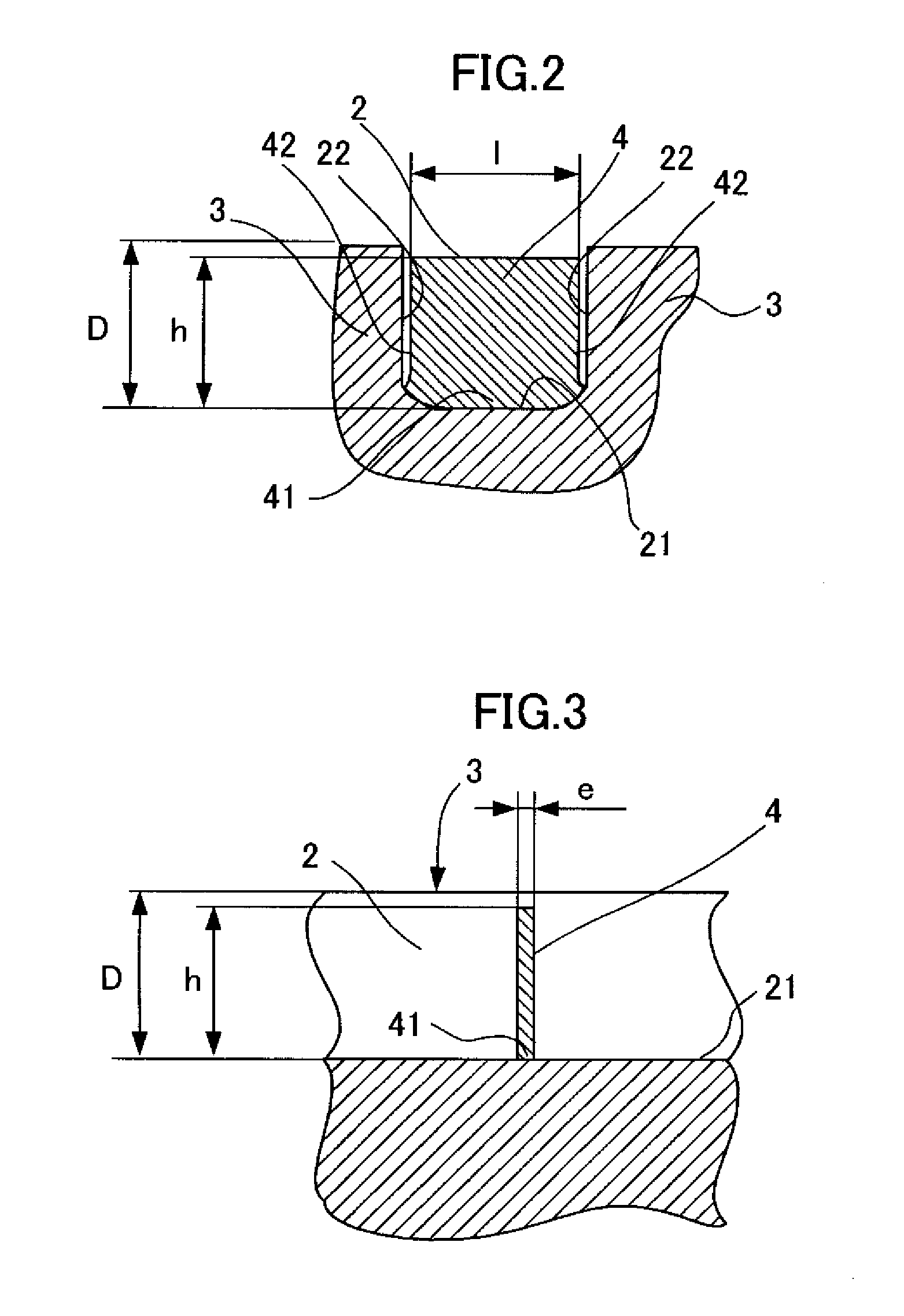
However, with the techniques disclosed in the abovementioned Patent literature article 1 and Patent literature article 2, in order for the groove fences to function, the groove fences are thin in the circumferential direction of the tire and deform readily, but there are problems in that depending on the material used groove fences which deform readily do not wear readily when being driven repeatedly, a difference arises between the amount of wear of the groove fence and that of the tread portion, and as a result the groove fence protrudes from the tread part and the groove fence hits the road surface generating an abnormal sound.
There is also a problem in that by virtue of the fact that the groove fence protrudes from the tread portion, unintended parts of the groove fence come into contact with the ground and are subjected to wear, and the groove fence becomes damaged when being driven.

Method used


Image

  • Pneumatic tire tread
  • Pneumatic tire tread
  • Pneumatic tire tread

Examples


embodiment

[0060]Next, in order to clarify the advantages of the present invention, an explanation will be given of the results of tests performed using a conventional example in which groove fences are not provided, a comparative example provided with groove fences, and a pneumatic tire according to embodiment 1 of the present invention.

[0061]The specimen tires according to the conventional example, the comparative example and embodiment 1 were in each case tires of size 225 / 55R16, the wheel size was 7.0J×16, and the pressure was set to 250 kPa.

[0062](1) Wear Performance:

[0063]Unused specimen tires were mounted, using the rims and at the pressure mentioned above, onto the four wheels of three identical vehicles (2000 cc displacement FR cars) which were driven in a three-vehicle convoy approximately 7,000 km on a prescribed asphalt test course with one driver in each vehicle, and the depths of the remaining grooves and the heights of the remaining groove fences were measured.

[0064](2) Drainage...


PUM


Abstract

A tread for a pneumatic tire in which air column resonance sound is reduced and wear of the groove fences and tread portion are caused to be approximately the same, while drainage performance is maintained, wherein a plurality of groove fences are formed and are installed within at least one circumferential groove, extending from the bottom of the circumferential groove, and block at least 70% of the cross-sectional area of the circumferential groove, and the bending parameter of the groove fences, defined as E·I / (h3l) (where E is the modulus at 10% elongation of the material used for the groove fences, I is the second moment of area of the groove fence, h is the height of the groove fence, and l is the width of the groove fence) is at least equal to 250 Pa and at most equal to 350 Pa.

Description

TECHNICAL FIELD[0001]The present invention relates to a tread for a pneumatic tire, and in particular relates to a tread for a pneumatic tire in which drainage performance can be maintained and air column resonance sound can be reduced by forming groove fences in circumferential grooves of the tread, while the groove fences can be caused to wear to a degree equivalent to that of the tread portion.BACKGROUND ART[0002]Air column resonance sound in circumferential grooves formed in tire treads is generated by means of resonance in a tube (air column) formed by the circumferential groove and the road surface, and the resonant frequency depends on the length of the air column formed between the circumferential groove and the road surface.[0003]This air column resonance sound manifests itself in the form of noise inside and outside the vehicle, and its peak is often at around 1 kHz, which readily reaches the human ear. As a technique for reducing the air column resonance noise of circumfe...

Claims


Application Information

Patent Timeline
IPC IPC(8): B60C11/13
CPCB60C11/1353B60C11/13B60C19/002B60C11/047B60C2011/1361
Inventor DAUTREY, NICOLASFUTAMURA, YASUHIROGREVERIE, LUDOVICROTY, GAELSHIMANAKA, NANAE
Owner MICHELIN & CO CIE GEN DES ESTAB MICHELIN
Learn More