Metal Sheet with Contour Cut for Vibration Reduction

a metal sheet and contour cutting technology, applied in the field of metal sheets, can solve problems such as damage, dislocation configurations, fatigue fractures, etc., and achieve the effects of preventing vibration transmission, decreasing stiffness gradient, and reducing stiffness of metal sheets

Active Publication Date: 2020-08-27
FRIEDRICH GRAEPEL AG
View PDF0 Cites 0 Cited by
  • Summary
  • Abstract
  • Description
  • Claims
  • Application Information

AI Technical Summary

Benefits of technology

[0009]By a contour cut is meant an incision in the material of the metal sheet which prevents a vibration transmission across the contour cut. The contour cut may be narrower than, but also broader than 1 mm. The contour cut can be introduced by lasering, punching, milling, cutting or the like in the material of the metal sheet.
[0010]According to one embodiment of the invention, the contour cut emerges at its ends in the direction transverse to the connection line into cut lines which are traced in an arc around the ends towards the connection line. The arc-shaped cut lines at the ends of the contour cut in the direction transverse to the connection line prevent the lines of force from ripping open the contour cut at these ends. Without the arc-shaped cut lines, the lines of force attacking the ends would form notch cracks, by which the contour cut would become increasingly longer and rip open. The arc-shaped cut lines divert the lines of force from the ends and divert them further into the surface of the metal sheet around the contour cut. A further unwanted ripping open of the contour cut transversely to the connection line is prevented in this way.
[0011]According to one embodiment of the invention, the contour cut is arranged in the area of the stress transition from the attachment point to the freely vibrating sheet. Owing to the connection of the attachment points to the support structure, the immediate surrounding region around an attachment point is more strongly braced against vibrational movements. The attachment point can be connected by screw, welding, gluing or some other joining technique to the support structure and thereby divert the acting forces into the support structure. Regardless of the joining technique used, the material of the metal sheet is much more rigid in the immediate surroundings of the attachment point by virtue of its bracing against the support structure than in other areas of the metal sheet. However, the supporting effect of the support structure on the material of the metal sheet diminishes with distance of the metal sheet away from the attachment point. The stiffness of the material of the metal sheet decreases very greatly in this region, while the vibration-caused stress in the material of the metal sheet increases greatly in this narrow transitional region. Without a contour cut, the stiffness gradient in this transitional region is very steep. In this region, due to the high stress found here in a narrow distance band away from the attachment point, stress increases and dislocation movements may occur as a consequence of vibrations. If a contour cut is made in this region of the stress transition, the stiffness gradient of the metal sheet decreases significantly in this region. Owing to the more shallow stiffness gradients, the stress loading in the transitional region and thus the risk of vibration-caused material failure also decreases. The positioning and geometry of the contour cut in this region naturally depends also on the geometry of the metal sheet and the technical requirements in the installation situation, which may make necessary a positioning of the contour cut adapted to these.
[0012]According to one embodiment of the invention, perforated sheets are used as the metal sheet. Perforated sheets with a rather large number of holes have a large hole fraction of, for example, more than 50% in relation to the overall surface of the metal sheet. The material webs between the holes are often very narrow, depending on the application and the hole pattern, for example in order to afford a low air resistance to air passing through in the case of ventilation grids or a high light pass-through rate for cover or protective grilles. Owing to the relatively slight remaining material fraction in the sheet surface, such perforated sheets can be more easily excited to vibrate than other sheets without perforation. Owing to the contour cuts in the region of the attachment points, however, the perforated sheets achieve significantly higher fatigue strength. In this way, the perforated sheets may also be used in applications where vibrations occur and which have thus far been reserved only for other technical solutions, such as wire grids or the like.
[0013]According to one embodiment of the invention, the attachment points and the contour cuts are arranged in the area of the outer edge of the metal sheet. By configuring the attachment points and the contour cuts in the area of the outer edge, the surface of the metal sheet can be fully utilized for the desired function. Such a configuration is also advantageous when the attachment of the metal sheet is only possible in the edge region of the metal sheet without impairing the function.

Problems solved by technology

In the further course of the straining, these result in dislocation configurations which may have a damaging effect due to a concentration of plastic deformations in very small regions.
These expand under further loading to form fatigue fractures.
The crystalline material of the metal sheet, however, will still be subjected to substantially diminished push and pull forces from the vibration-caused peak forces.

Method used


Image

  • Metal Sheet with Contour Cut for Vibration Reduction
  • Metal Sheet with Contour Cut for Vibration Reduction
  • Metal Sheet with Contour Cut for Vibration Reduction

Examples


Embodiment Construction

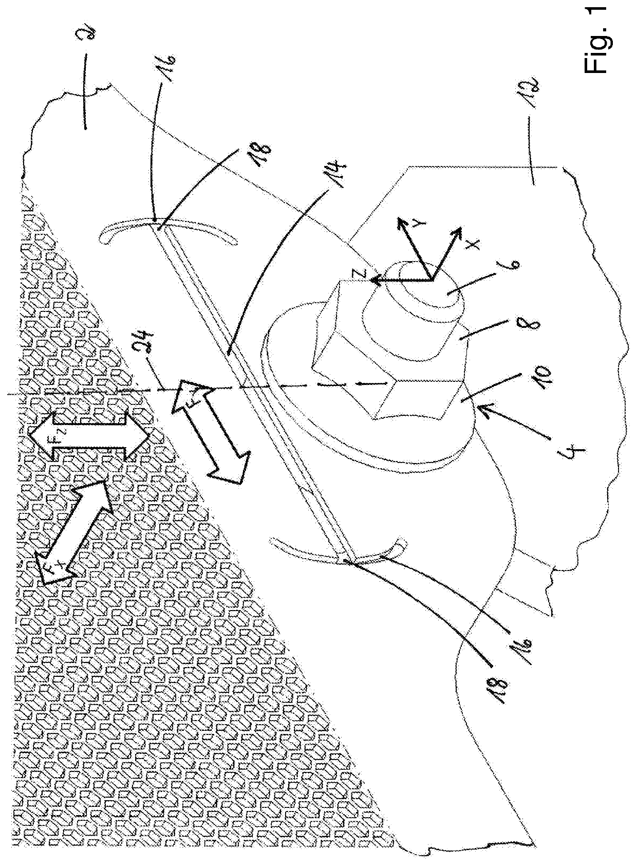
[0020]FIG. 1 shows a view of a metal sheet 2, being configured in the exemplary embodiment as a perforated sheet. The metal sheet 2 is joined by an attachment point 4 to a support structure 12. The connection is produced in the exemplary embodiment by a screw 6, which is joined to the support structure 12. For the joining of the metal sheet 2 to the support structure 12, a screw nut 8 with a washer 10 underneath is screwed onto the screw 6. By this connection, the metal sheet 2 is firmly held in the support structure 12.

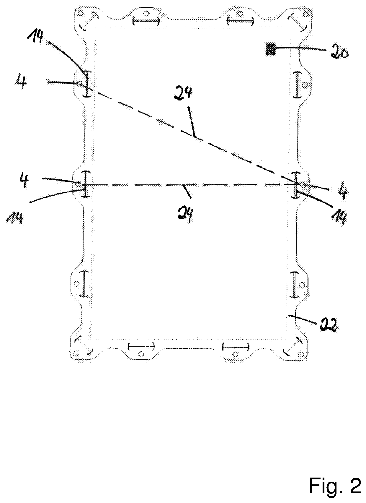
[0021]Besides the attachment point represented in FIG. 1, the metal sheet 2 is further joined by at least one additional attachment point 4 to the support structure 12. The metal sheet 2 is thus secured in its installation position at least at two points.

[0022]Adjacent to the attachment point 4 there is a contour cut 14 in the metal sheet 2. The contour cut 14 is an incision in the metal sheet 2 extending transversely to a connection line 24 indicated by broken lines...


PUM

PropertyMeasurementUnit
stress transitionaaaaaaaaaa
areaaaaaaaaaaa
stiffnessaaaaaaaaaa

Abstract

A metal sheet with attachment points for attaching the metal sheet to a support structure has a contour cut introduced in a sheet surface of the metal sheet, wherein the contour cut extends transversely to a connection line extending between a first and a second one of the attachment points. The contour cut is positioned relative to the first attachment point such that a vibration line extending as far as the first attachment point when the contour cut is not present is interrupted by the contour cut.

Description

BACKGROUND OF THE INVENTION[0001]The present invention relates to a metal sheet with cutouts in the sheet surface and a plurality of attachment points to a support structure.[0002]A metal sheet needs to have good stiffness and good buckling strength for many applications and furthermore it needs to be economical and easy to fabricate. Metal sheets are often single-piece, that is, made from a single sheet blank. A sheet blank is often subjected to numerous punching and forming procedures in order to obtain the desired form of the metal sheet. Often a sheet blank is used with a smaller sheet thickness and made from a material of lesser strength in order to facilitate the various forming, perforating and punching procedures during the machining of the metal sheet. The relatively soft sheet material makes possible the corresponding machining procedures without the material ripping or breaking in this process. Metal sheets are likewise known that are fabricated from a sheet blank and not...

Claims


Application Information

Patent Timeline
Patent Type & Authority Applications(United States)
IPC IPC(8): B21D28/10B21D26/021B21D5/02
CPCB21D26/021B21D5/0209B21D28/10Y10T428/12215B21D35/008F16F15/02F16F2230/0029B21D28/00B21D28/24B21D28/26F16F15/34F16F2230/36Y10T428/12361
Inventor HARTWICH, EWALDBARTKE, MARCWILLIMEK, NORMANN
Owner FRIEDRICH GRAEPEL AG
Why Eureka
Try Eureka