Self-compensating filament tension control device with friction band braking

a self-compensation, tension control technology, applied in the direction of filament handling, thin material processing, transportation and packaging, etc., can solve the problems of unfavorable use of tension control devices, and often multiple individual adjustments of creels having variable tension control

Active Publication Date: 2014-01-09
RJS
View PDF0 Cites 4 Cited by
  • Summary
  • Abstract
  • Description
  • Claims
  • Application Information

AI Technical Summary

Benefits of technology

[0012]Another aspect of the present invention is to provide a self-compensating tension control device for regulating the withdrawal of filamentary material from a spool, comprising a fixed support, the fixed support maintaining a cam surface, a spindle assembly carried by the fixed support, the spindle assembly rotatably carrying the spool of filamentary material, wherein a tension force applied to the filamentary material, in opposition to a biasing force, causes the spindle assembly to linearly move in relation to the fixed support, and a braking mechanism comprising a brake drum rotatable with the spindle assembly, a friction band adapted to engage the brake drum, and a rocker arm having a cam roller engageable with the cam surface at one end and at an opposite end a bracket associated with the friction band, wherein when the tension force applied to the filamentary material is reduced and unable to overcome the biasing force, the cam roller engages the cam surface and causes the bracket and the friction band to generate a braking force on the brake drum, and wherein withdrawal of the filamentary material at a regulated rate occurs when the biasing force is balanced with the tension force.

Problems solved by technology

In the past, such creels having variable tension control have often required multiple individual adjustments and have not been desirably compact.
In other instances, creels have exhibited undesirable hunting or loping in the form of periodic variations about a desired tension, particularly in high-tension applications.
However, there are several situations in which these tension control devices are not well suited.
It has been found that the control arm and guide roller are vulnerable to damage from over-tension possibly caused by entanglement of the spooled material.
This may lead to a less than satisfactory end product or the need to provide additional manufacturing equipment to straighten the wire.
To the present time, there has been no comprehensive device for adequately dispensing heavy filamentary material from a spool.
Yet a third problem is that the control arm and roller inhibits closely mounting the multiple tension controllers on the creel assembly.
However, the use of a control arm has the problems previously mentioned of imparting distortion to the filamentary material, damaging the guide roller from over-tension and preventing such devices from being closely mounted to one another on the creel assembly.

Method used


Image

  • Self-compensating filament tension control device with friction band braking
  • Self-compensating filament tension control device with friction band braking
  • Self-compensating filament tension control device with friction band braking

Examples


Embodiment Construction

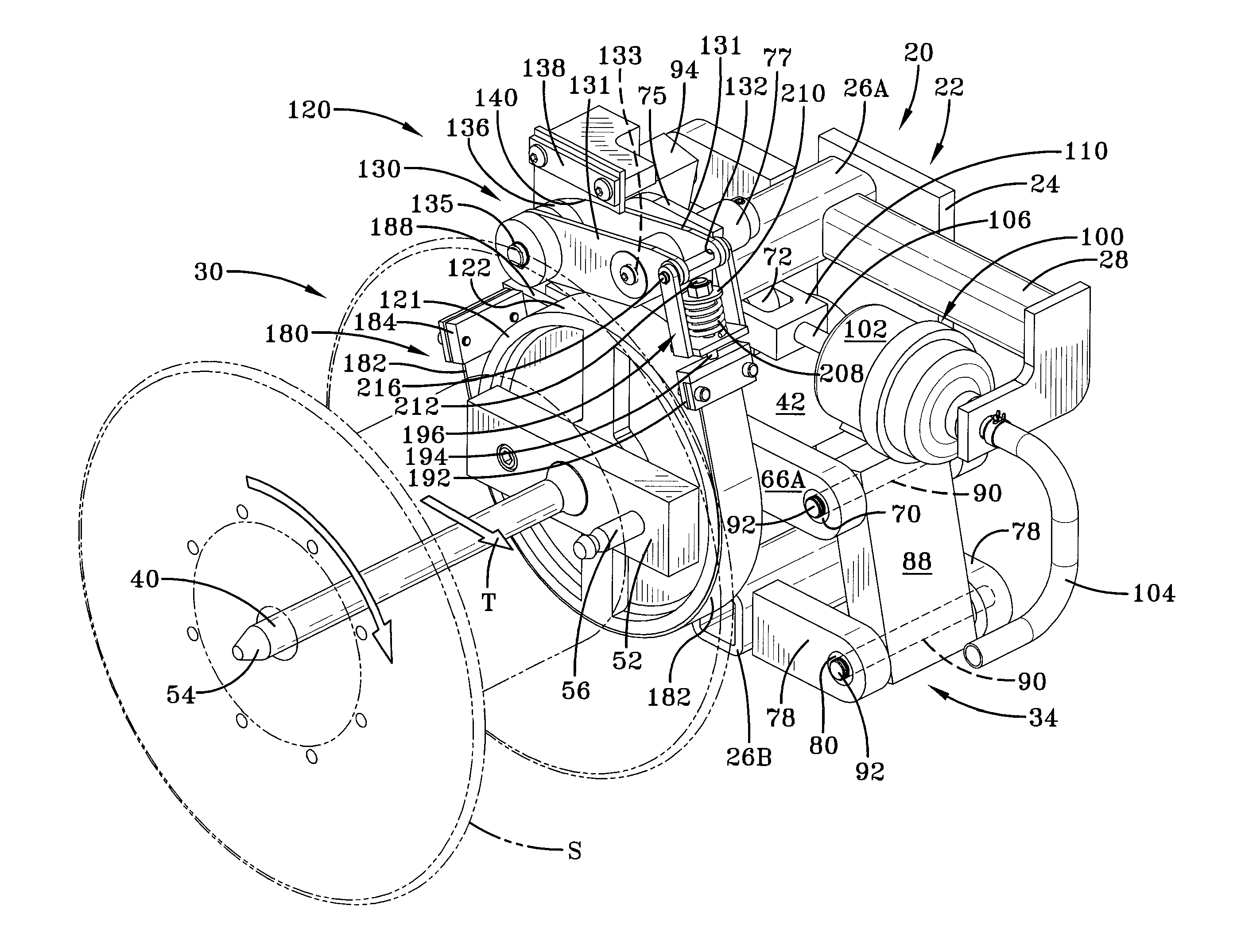
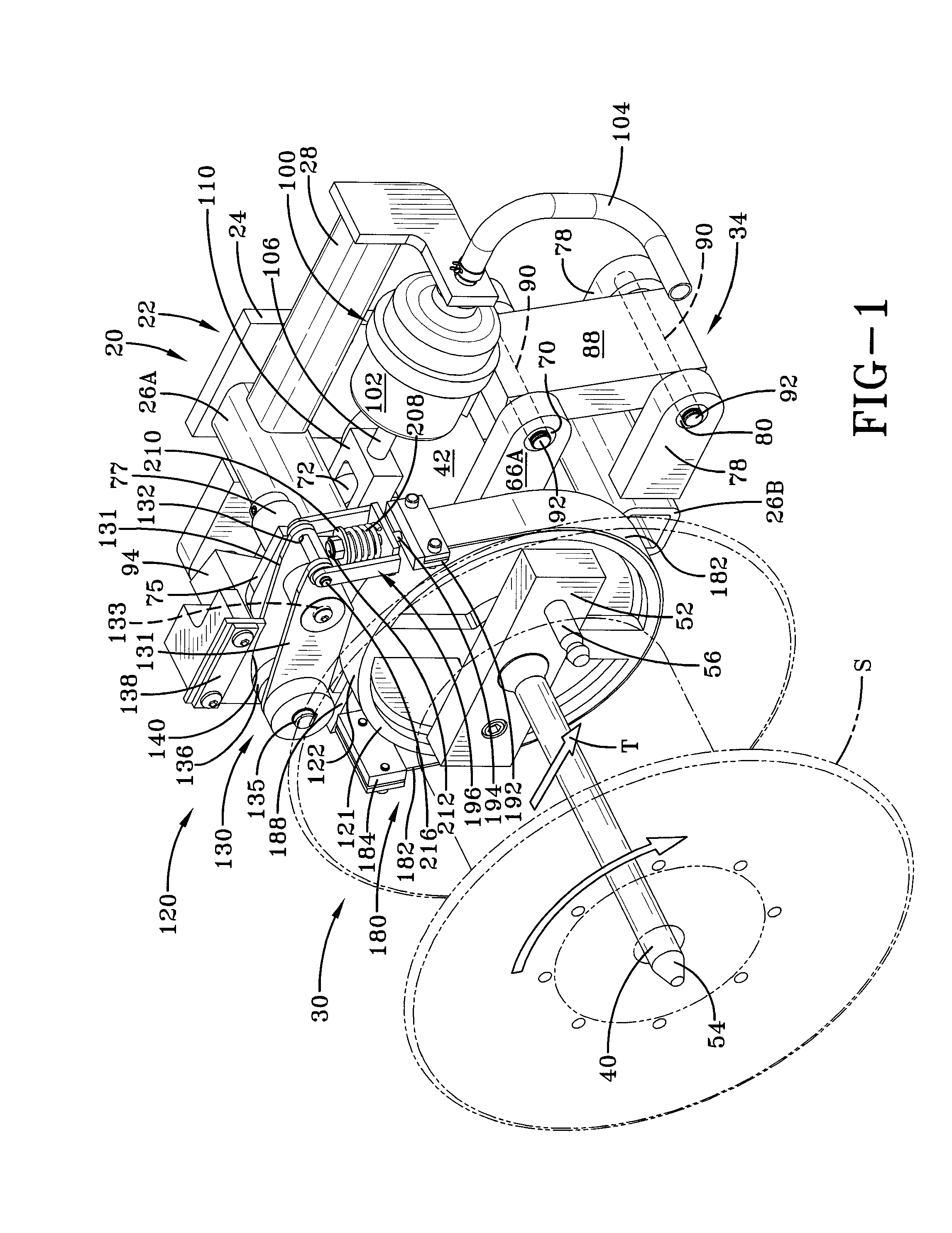
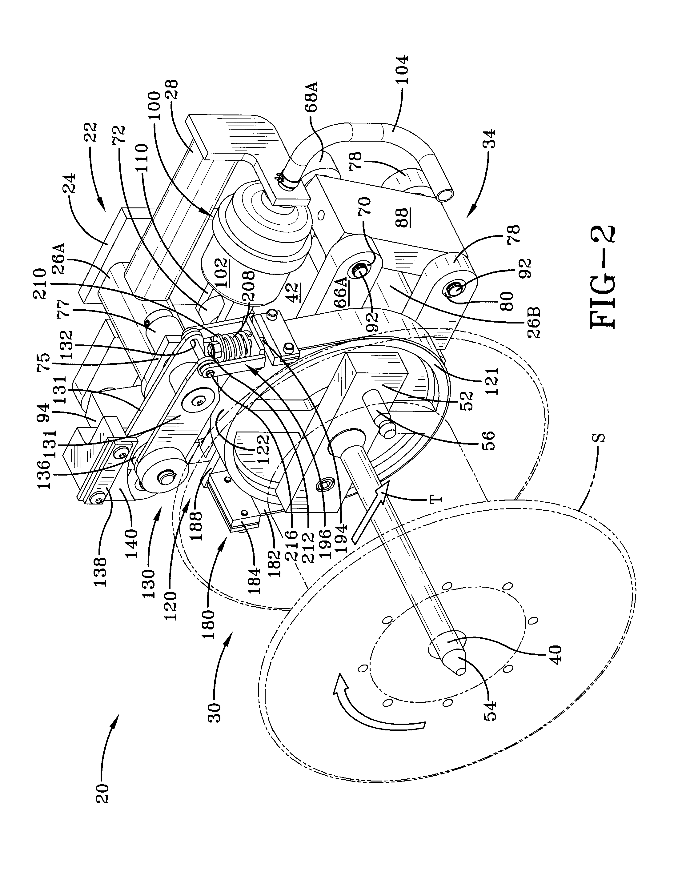
[0030]An exemplary self-compensating filament tension control device with friction band braking according to the concepts of the present invention is generally indicated by the numeral 20 as seen in FIGS. 1-8. The tension control device 20 includes a fixed support 22 that is affixed to or is part of a creel or other support structure which is part of a machine that processes individual strands of filamentary material into a finished manufactured item. It will be appreciated that the creel likely supports multiple devices 20 as needed. The fixed support 22 includes a support frame 24 which is mounted on the creel via bolts, welding or other secure attachment. The support frame 24 includes an upper support arm 26A and a lower support arm 26B extending substantially perpendicularly therefrom and wherein the support arms 26 are utilized to support or carry other components of the control device 20. A diaphragm actuator bracket 28 extends perpendicularly and outwardly from the upper supp...


PUM


Abstract

A self-compensating tension control device for regulating the withdrawal of filamentary material from a spool includes a fixed support that maintains an inverted cam surface and a spindle assembly rotatably carrying the spool. A tension force applied to the filamentary material, in opposition to a biasing force, moves the spindle assembly linearly in relation to the fixed support. A braking mechanism includes a brake drum rotatable with the spindle assembly, a friction band adapted to engage the brake drum and a rocker arm that engages the cam surface. When the tension force applied to the filamentary material is reduced and unable to overcome the biasing force, the cam roller engages the cam surface and causes the friction band to generate a braking force on the brake drum.Withdrawal of the filamentary material at a regular rate occurs when the biasing force is balanced with the tension force.

Description

TECHNICAL FIELD[0001]The present invention relates generally to an automatic tension control device for regulating the amount of tension under which a filamentary material is withdrawn from a spool. More particularly, the present invention relates to such a tension control device which tends to maintain substantially constant tension in filamentary materials over variances in operating parameters. More specifically, the present invention relates to such a tension control device which employs a laterally movable spindle carriage operative with a cam-actuated friction band brake, thereby tending to maintain substantially constant tension in the filament.BACKGROUND ART[0002]Filamentary materials include fibers in single and multiple strands, flat bands, or tubing produced in long lengths and conveniently wound on spools. The various filamentary materials may be either natural or synthetic fibers, glass or metal. Such materials are commonly utilized as reinforcements for plastic or elas...

Claims


Application Information

Patent Timeline
Patent Type & Authority Applications(United States)
IPC IPC(8): B65H59/04
CPCB65H59/04
Inventor SLEZAK, RAYMOND J.
Owner RJS
Why Eureka
Try Eureka