Optical image capturing system

a technology of optical image and ring system, which is applied in the field of miniaturized optical image capture system, can solve the problems of not being applicable to portable electronic products with a compact size, the assembly of many lens elements is usually too bulky to have its size miniaturized, and the requirement of high-end optical systems with camera functionalities

Active Publication Date: 2014-01-09
LARGAN PRECISION
View PDF1 Cites 167 Cited by
  • Summary
  • Abstract
  • Description
  • Claims
  • Application Information

AI Technical Summary

Benefits of technology

[0042]By such an arrangement, the configuration of the surface curvature of the seventh lens element is favorable for the disposition of the other lens elements, the arrangement of the aspheric surface of the other lens elements and the arrangement of the inflection point to correct the high order aberration and the off-axis aberrations, for example, the comatic aberration and the astigmatism, and to reduce the angle at which the incident light projects onto the image sensor from the off-axis field under a certain total track length and to realize an optical image capturing system with a better image quality and a compact size.

Problems solved by technology

However, the conventional optical systems cannot satisfy the requirements of high-end optical systems with camera functionalities.
A conventional optical image lens assembly with many lens elements is usually too bulky to have its size being miniaturized; therefore, it is not its applicable to portable electronic products with a compact size.
An optical image lens assembly with five lens elements, such as “Imaging Lens Assembly” disclosed in U.S. Pat. No. 8,000,030, lacks good ability to correct high order aberrations and off-axis aberrations.
Moreover, the space arrangement, the distribution of refractive power and the design of lens surface are not favorable to have its total track of length being effectively shortened thereof and it is thereby not easy to have a compact size with good image quality.

Method used


Image

  • Optical image capturing system
  • Optical image capturing system
  • Optical image capturing system

Examples


1st embodiment

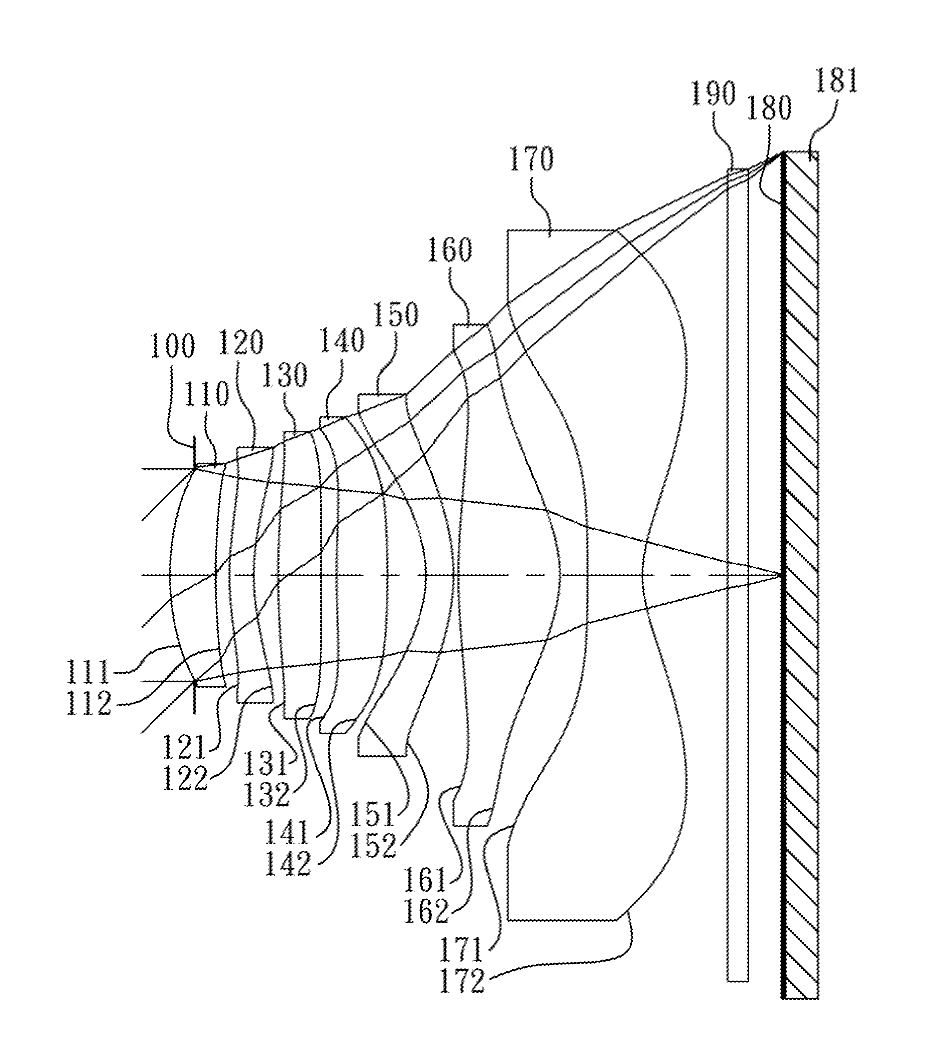
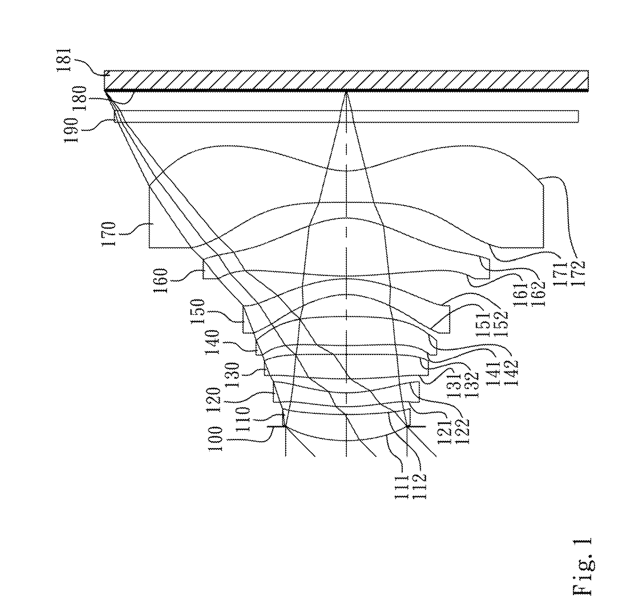
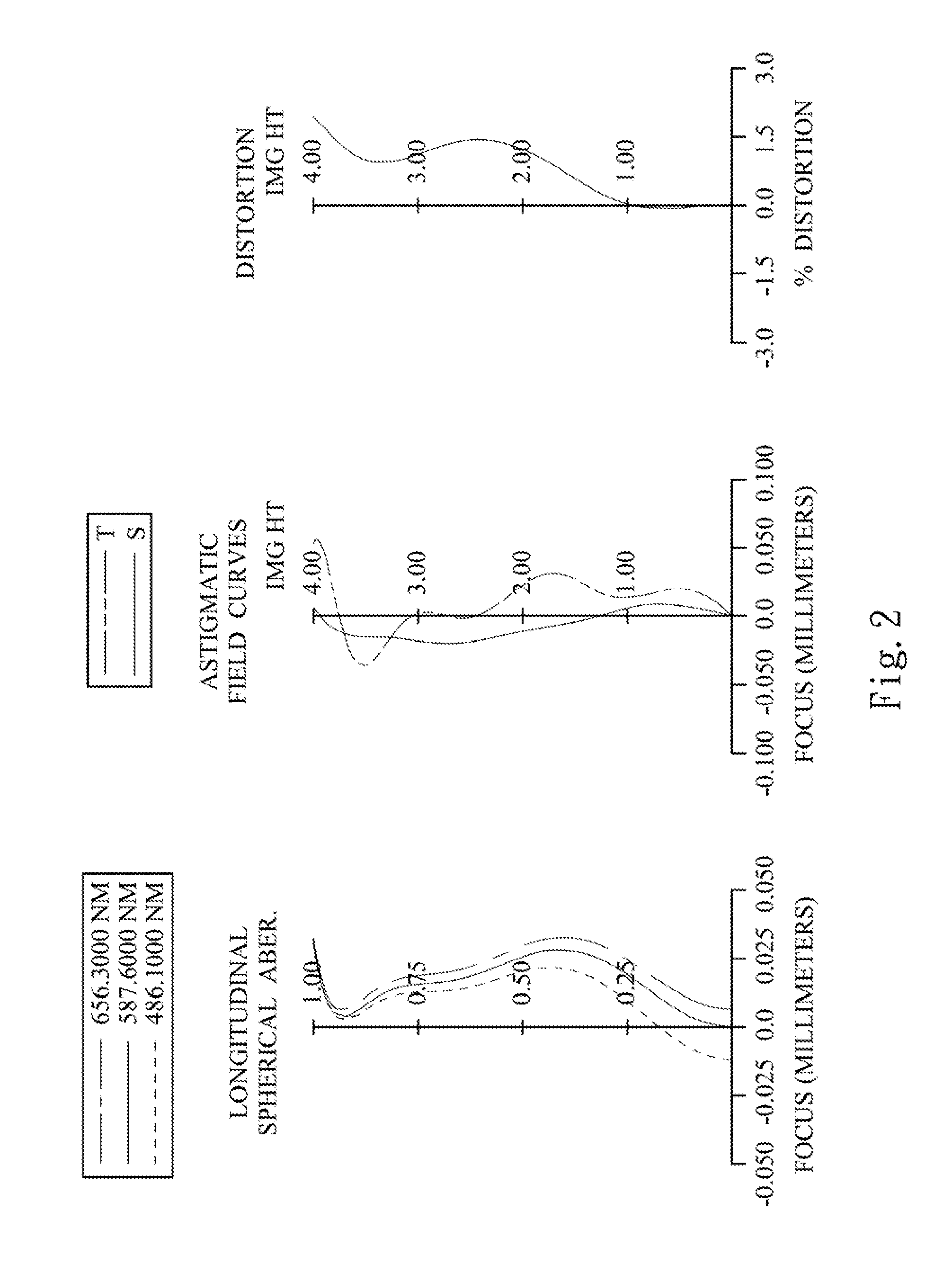
[0075]FIG. 1 is a schematic view of an optical image capturing system according to the 1st embodiment of the present disclosure. FIG. 2 shows, in order from left to right, spherical aberration curves, astigmatic field curves and a distortion curve of the optical image capturing system according to the 1st embodiment.

[0076]In FIG. 1, the optical image capturing system includes, in order from an object side to an image side, an aperture stop 100, a first lens element 110, a second lens element 120, a third lens element 130, a fourth lens element 140, a fifth lens element 150, a sixth lens element 160, a seventh lens element 170, an IR-cut filter 190, an image plane 180 and an image sensor 181.

[0077]The first lens element 110 with positive refractive power has a convex object-side surface 111 and a concave image-side surface 112, which are both aspheric, and the first lens element 110 is made of plastic material.

[0078]The second lens element 120 with negative refractive power has a con...

2nd embodiment

[0105]FIG. 3 is a schematic view of an optical image capturing system according to the 2nd embodiment of the present disclosure. FIG. 4 shows, in order from left to right spherical aberration curves, astigmatic field curves and a distortion curve of the optical image capturing system according to the 2nd embodiment.

[0106]In FIG. 3, the optical image capturing system includes, in order from an object side to an image side, a first lens element 210, an aperture stop 200, a second lens element 220, a third lens element 230, a fourth lens element 240, a fifth lens element 250, a sixth lens element 260, a seventh lens element 270, an IR-cut filter 290, an image plane 280 and an image sensor 281.

[0107]The first lens element 210 with positive refractive power has a convex object-side surface 211 and a concave image-side surface 212, which are both aspheric, and the first lens element 210 is made of plastic material.

[0108]The second lens element 220 with negative refractive power has a conv...

3rd embodiment

[0118]FIG. 5 is a schematic view of an optical image capturing system according to the 3rd embodiment of the present disclosure. FIG. 6 shows, in order from left to right, spherical aberration curves, astigmatic field curves and a distortion curve of the optical image capturing system according to the 3rd embodiment.

[0119]In FIG. 5, the optical image capturing system includes, in order from an object side to an image side, an aperture stop 300, a first lens element 310, a second lens element 320, a third lens element 330, a fourth lens element 340, a fifth lens element 350, a sixth lens element 360, a seventh lens element 370, an IR-cut filter 390, an image plane 380 and an image sensor 381.

[0120]The first lens element 310 with positive refractive power has a convex object-side surface 311 and a concave image-side surface 312, which are both aspheric, and the first lens element 310 is made of plastic material.

[0121]The second lens element 320 with negative refractive power has a con...


PUM


Abstract

An optical image capturing system includes, in order from an object side to an image side, a first lens element, a second lens element, a third lens element, a fourth lens element, a fifth lens element, a sixth lens element and a seventh lens element. The first lens element with positive refractive power has a convex object-side surface. The second through seventh lens elements all have refractive power. The sixth lens element has an object-side surface and an image-side surface which are both aspheric. The seventh lens element has an object-side surface and an image-side surface which are both aspheric, its wherein the image-side surface of the seventh lens element changes from concave at a paraxial region thereof to convex at a peripheral region thereof.

Description

RELATED APPLICATIONS[0001]The present application is a continuation of the application Ser. No. 13 / 669,445, filed Nov. 6, 2012, the entire contents of which are hereby incorporated herein by reference, which claims priority to Taiwan Application Serial Number 101124430, filed Jul. 6, 2012, all of which are herein incorporated by reference.BACKGROUND[0002]1. Technical Field[0003]The present disclosure relates to an optical image cap ring system. More particularly, the present invention relates to a miniaturized optical image capturing system applicable to electronic products.[0004]2. Description of Related Art[0005]In recent years, with the popularity of mobile products with camera functionalities, a demand for optical system is increasing. A photosensitive sensor of a conventional optical system is typically a CCD (Charge-Coupled Device) or a CMOS (Complementary Metal-Oxide-Semiconductor) sensor. As advanced semiconductor manufacturing technologies have allowed a pixel size of senso...

Claims


Application Information

Patent Timeline
Patent Type & Authority Applications(United States)
IPC IPC(8): G02B13/18
CPCG02B13/18G02B13/0045G02B9/64G02B3/04G02B13/00G02B13/0015G02B13/002H04N23/55G02B27/0025
Inventor TSAI, TSUNG-HANHUANG, HSIN-HSUAN
Owner LARGAN PRECISION
Why Eureka
Try Eureka