

Photographing optical lens assembly
a technology of optical lens and lens assembly, which is applied in the field of photographing optical lens assembly, can solve the problems of insufficient high-end photo processing modules, difficult to reduce the total track length of lenses, and the inability of the optical lens system to take images to maintain a compact form, so as to reduce the size of lens assemblies, reduce the sensitivity of optical systems, and improve the effect of resolution
- Summary
- Abstract
- Description
- Claims
- Application Information
AI Technical Summary
Benefits of technology
Problems solved by technology
Method used
Image

Examples
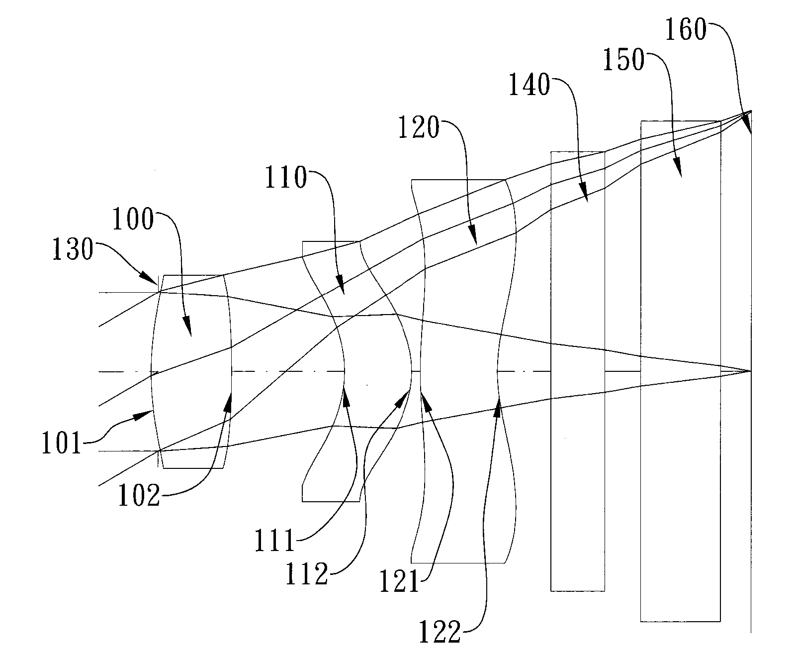
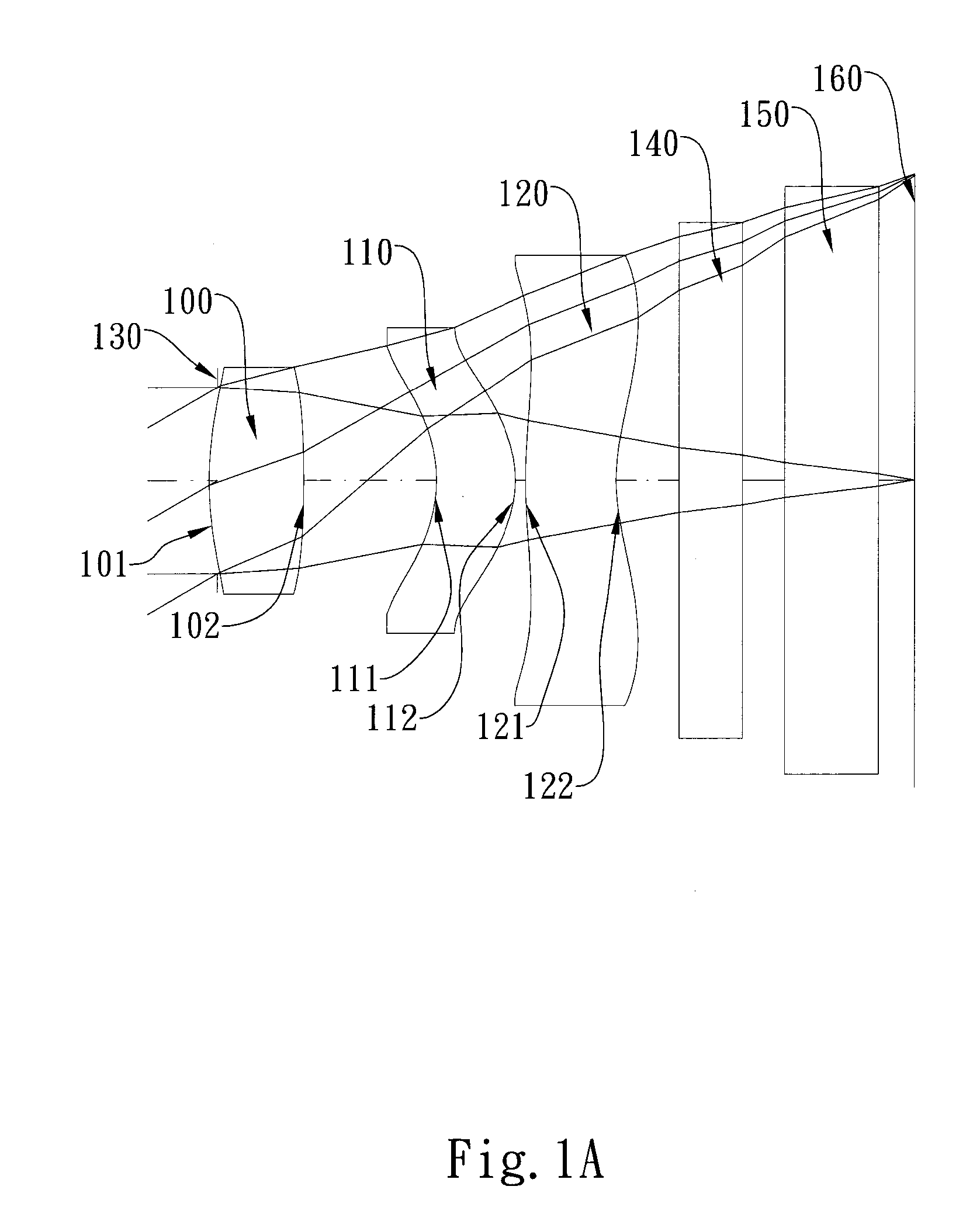
first embodiment
[0067]In the present photographing optical lens assembly, the focal length of the photographing optical lens assembly is f, and it satisfies the relation: f=2.51 (mm).
[0068]In the first embodiment of the present photographing optical lens assembly, the f-number of the photographing optical lens assembly is Fno, and it satisfies the relation: Fno=2.84.
[0069]In the first embodiment of the present photographing optical lens assembly, half of the maximal field of view of the photographing optical lens assembly is HFOV, and it satisfies the relation: HFOV=30.0 deg.
[0070]In the first embodiment of the present photographing optical lens assembly, the Abbe number of the first lens element 100 is V1, the Abbe number of the second lens element 110 is V2, the Abbe number of the third lens element 120 is V3, and they satisfy the relations: |V1−V2|=0.0, |V1−V3|=0.0.
[0071]In the first embodiment of the present photographing optical lens assembly, the thickness of the first lens element 100 near t...
second embodiment
[0086]In the present photographing optical lens assembly, the focal length of the photographing optical lens assembly is f, and it satisfies the relation: f=4.64 (mm).
[0087]In the second embodiment of the present photographing optical lens assembly, the f-number of the photographing optical lens assembly is Fno, and it satisfies the relation: Fno=2.73.
[0088]In the second embodiment of the present photographing optical lens assembly, half of the maximal field of view of the photographing optical lens assembly is HFOV, and it satisfies the relation: HFOV=30.5 deg.
[0089]In the second embodiment of the present photographing optical lens assembly, the Abbe number of the first lens element 200 is V1, the Abbe number of the second lens element 210 is V2, the Abbe number of the third lens element 220 is V3, and they satisfy the relations: |V1−V2|=25.7, |V1−V3|=32.5.
[0090]In the second embodiment of the present photographing optical lens assembly, the thickness of the first lens element 200 ...
third embodiment
[0105]In the present photographing optical lens assembly, the focal length of the photographing optical lens assembly is f, and it satisfies the relation: f=4.17 (mm).
[0106]In the third embodiment of the present photographing optical lens assembly, the f-number of the photographing optical lens assembly is Fno, and it satisfies the relation: Fno=2.85.
[0107]In the third embodiment of the present photographing optical lens assembly, half of the maximal field of view of the photographing optical lens assembly is HFOV, and it satisfies the relation: HFOV=33.5 deg.
[0108]In the third embodiment of the present photographing optical lens assembly, the Abbe number of the first lens element 300 is V1, the Abbe number of the second lens element 310 is V2, the Abbe number of the third lens element 320 is V3, and they satisfy the relations: |V1−V2|=0.0, |V1−V3|=0.0.
[0109]In the third embodiment of the present photographing optical lens assembly, the thickness of the first lens element 300 near t...
PUM
 Abstract
Description
Claims
Application Information