Variable ratio steering gear

a technology of steering gear and variable ratio, which is applied in the direction of steering gears, steering controls, power driven steering, etc., can solve the problem that the device is not suitable for use on the power assisted steering gear, and achieve the effect of being made availabl

Inactive Publication Date: 2005-09-20
BISHOP STEERING TECH
View PDF11 Cites 29 Cited by
  • Summary
  • Abstract
  • Description
  • Claims
  • Application Information

AI Technical Summary

Benefits of technology

[0039]The side-shifting of the pinion is so arranged that it subtracts from the output of the rack and pinion and can quite readily be made so as to provide a centre steering ratio of any magnitude that may be required.

Problems solved by technology

A problem arises, however, in having a mechanical back-up device reasonably mimic the performance of the electronic device, so that, if a transition to mechanical from electronic operation occurred at high speed or in a corner, the driver has the best chance of retaining control of the vehicle.
Such a device is not suited for use on a power assisted steering gear and is an undesirable arrangement in that the signal to increase the output near centre is derived from the modified output and not the input.

Method used


Image

  • Variable ratio steering gear
  • Variable ratio steering gear
  • Variable ratio steering gear

Examples


first embodiment

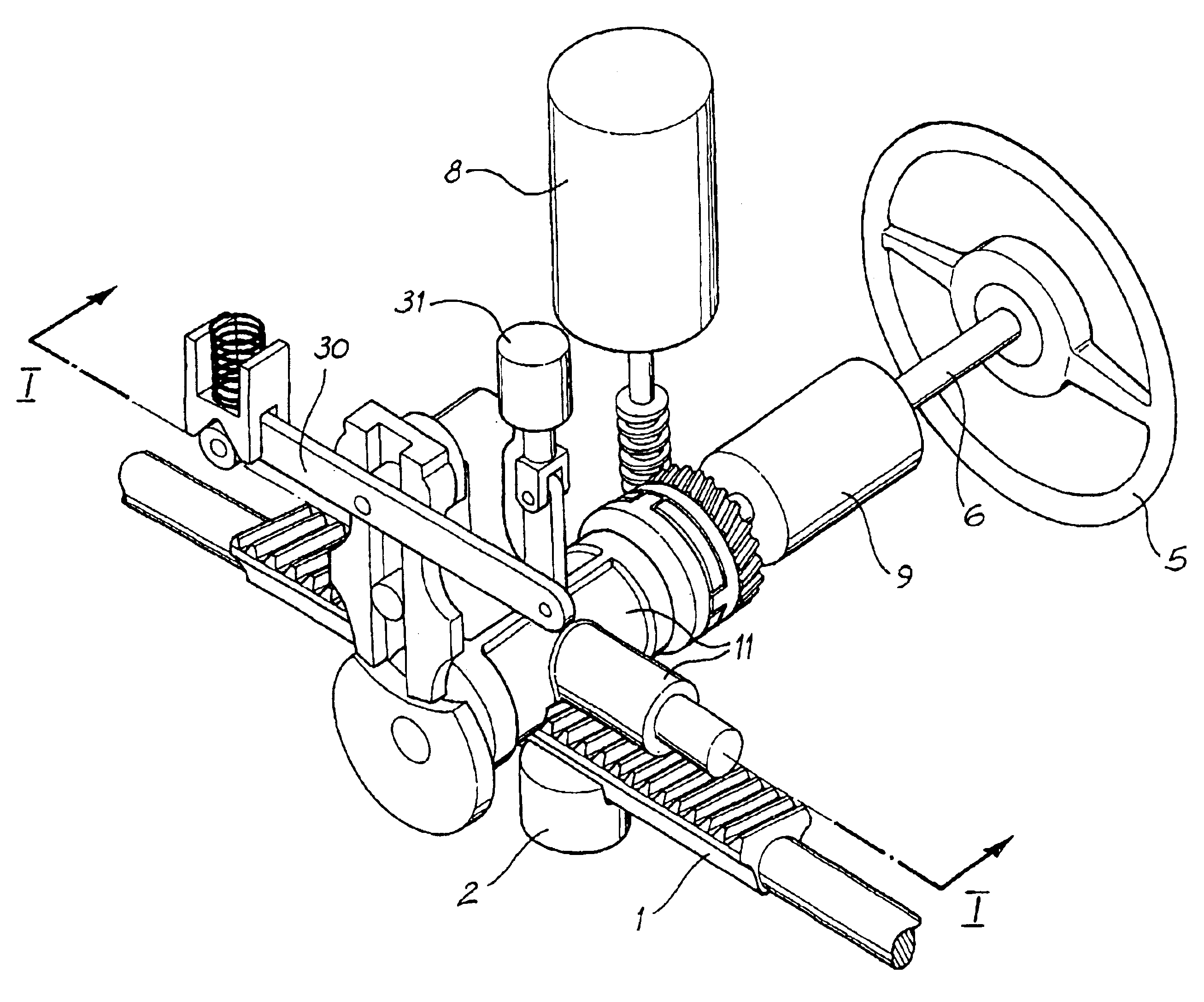
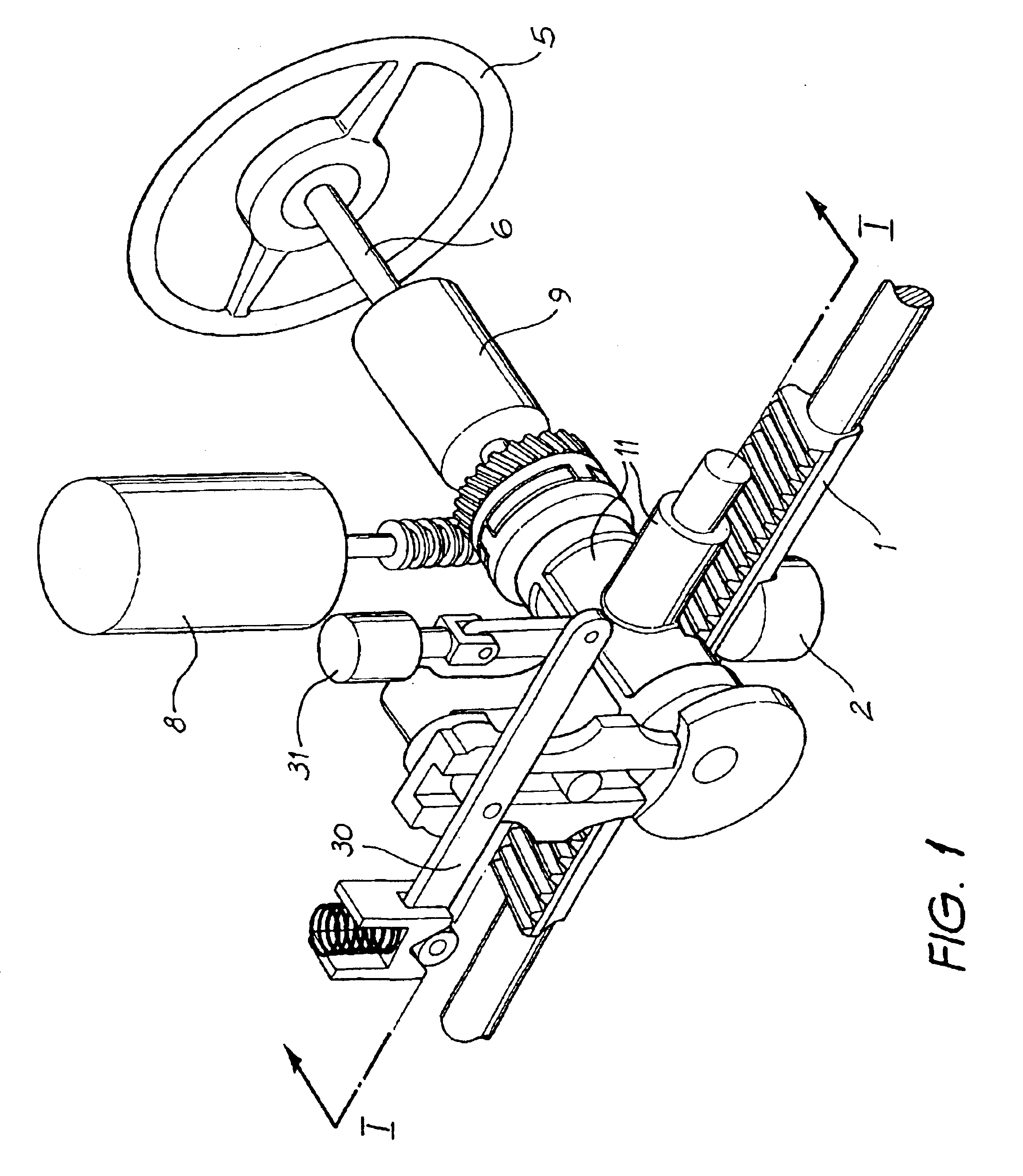
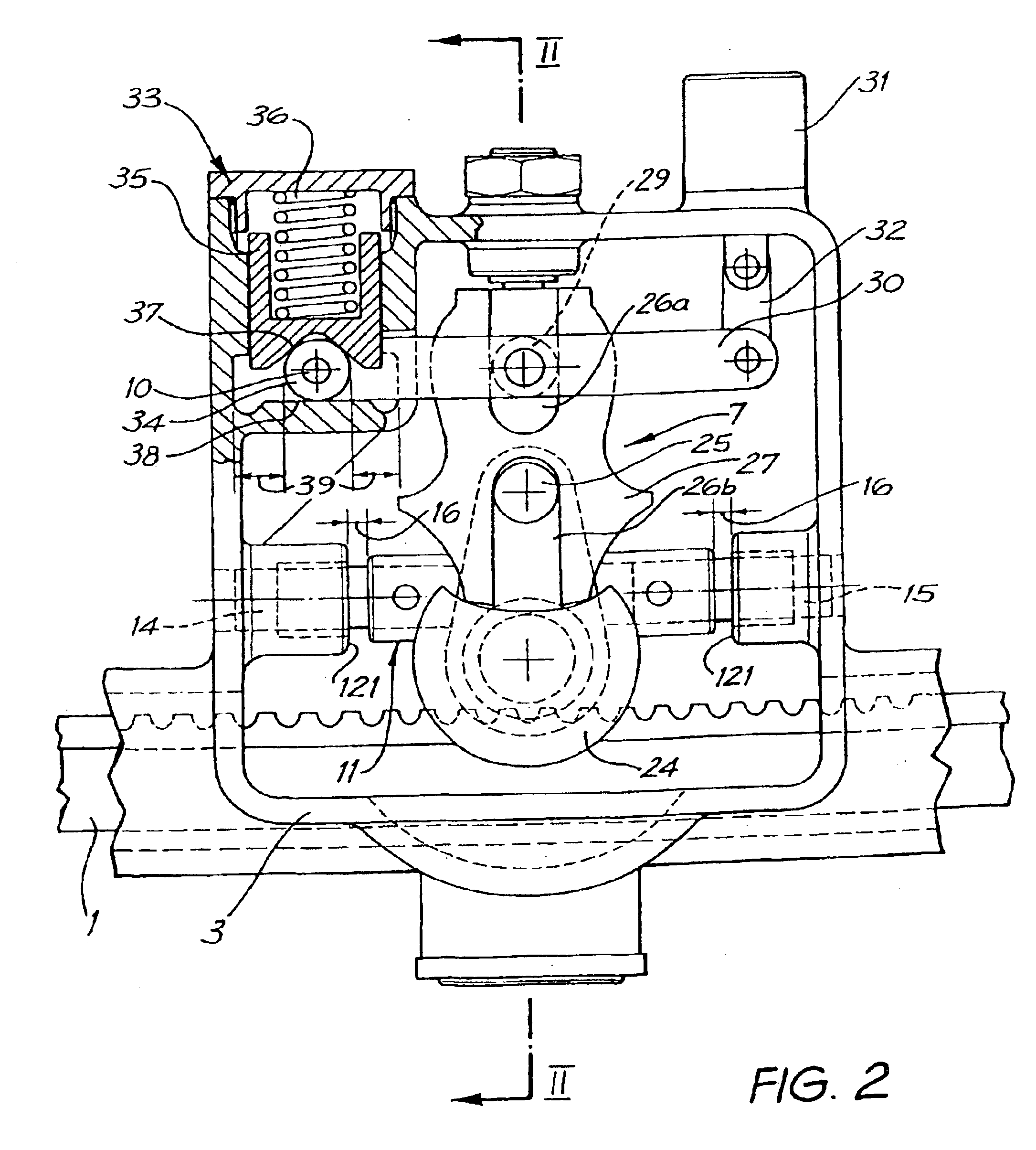
[0050]FIGS. 1, 2 and 3 show the general arrangement of the main components of one configuration of the steering gear made according to the invention.

[0051]Rack 1 and pinion 4 are constructed according to the widely accepted arrangement employed in rack and pinion steering gears. Tie rods (not shown) are connected to each end of the rack and are pivoted to steering arms extending rearwardly or forwardly from the pivoted front wheels of the vehicle. Rack 1 slides in rack guide 2, incorporated in housing 3 (FIGS. 2 and 3) at one side of the vehicle and in a journal (not shown) on the opposite side of the vehicle. Pinion 4 engages rack 1 in the conventional manner and is connected to rotate with steering wheel 5 by steering column 6.

[0052]In the form of steering gear to be described, electric motor driven power assistance is provided from electric motor 8. The operation of motor 8 is controlled by torque sensing device 9. Alternatively, hydraulic power-assist may be provided by employin...

second embodiment

[0087]FIG. 12 shows a simplified view of a steering gear using a desmodromic cam mechanism instead of a geneva mechanism. The components of the steering gear that are not shown on FIG. 12 are the same as the steering gear shown in FIGS. 2 and 3.

[0088]Comparing the desmodromic cam mechanism shown in FIG. 12 with the simplified geneva mechanism shown in FIG. 4, desmodromic cams 126a and 126b replaces geneva drive pin 25 and locking plate sector 24, and follower arm 127 replaces geneva driven plate 27.

[0089]Pin 29 attached to speed lever 30 engages slot 130 formed in follower arm 127. Shaft 28 which projects from follower arm 127 is journalled in pinion carrier 11 about axis 41. Vertical distance 103 is the distance between axis 41 and axis 104 of pin 29. Distance 103, in a like manner to the first embodiment, is varied by servo motor 31 to incline speed lever 30 about pivot 10. Similarly, at high vehicle speed, distance 103 is greater than at low vehicle speed.

[0090]Roller 128a attach...


PUM


Abstract

A rack (1) and pinion (4) steering gear for a vehicle in which the steering angle ratio varies as a function of at least both the steering wheel angle input by the driver and vehicle speed. The steering gear comprising a rack (1) laterally displacable with respect to a steering gear housing and a pinion (4) laterally movable within the housing substantially in a direction of travel of the rack (1) whilst engaged with the rack (1). The steering angle ratio is increased in a central region of travel of the rack (1) when compared to regions either side thereof, and steering angle ratio is further increased in the central region as vehicle speed increases.

Description

[0001]This application is the national phase under 35 U.S.C. § 371 of PCT International Application No. PCT / AU01 / 01399 which has an International filing date of Oct. 30, 2001, which designated the United States of America.TECHNICAL FIELD[0002]The present invention relates to a Variable Ratio Steering Gear in which the ratio between the driver's control device and the road wheels varies firstly in accordance with vehicle speed and secondly in accordance with the angle of turn from centre of the road wheels. More particularly the invention is directed towards a Variable Ratio Steering Gear in which the ratio between the amplitude of the driver's input to the control device and the turning of the road wheels(hereinafter referred to as the steering ratio) increases within a central region of the rack and further increases the central region of the rack as vehicle speed increases.BACKGROUND[0003]Various devices have been described in the literature and patents which seek to accomplish th...

Claims


Application Information

Patent Timeline
Patent Type & Authority Patents(United States)
IPC IPC(8): B62D3/00B62D3/12B62D9/00B62D6/02B62D1/16B62D5/22F16H19/04
CPCB62D1/166B62D3/12B62D6/02
Inventor BISHOP, ARTHUR ERNEST
Owner BISHOP STEERING TECH
Why Eureka
Try Eureka