Image pick-up optical lens assembly

a technology of optical lens and assembly, applied in the field of can solve the problems of insufficient three-element lens assembly for high-end imaging lens modules, the standard for image quality becomes even higher, and the pixel size of sensors will become even smaller, so as to facilitate a significant reduction in the size and sensitivity of the lens assembly, and the effect of reducing the total track length of the image pick-up optical lens assembly

Active Publication Date: 2011-11-29
LARGAN PRECISION
View PDF4 Cites 34 Cited by
  • Summary
  • Abstract
  • Description
  • Claims
  • Application Information

AI Technical Summary

Benefits of technology

[0010]Such arrangement facilitates a significant reduction in the size and sensitivity of the lens assembly and enables the lens assembly to obtain a higher resolution.
[0011]In the present image pick-up optical lens assembly, the first lens element with positive refractive power provides a part of the refractive power for the optical system so that the total track length of the image pick-up optical lens assembly can be favorably reduced; the second lens element has negative refractive power so that the aberration generated by the first lens element with positive refractive power and the chromatic aberration of the optical system can be favorably corrected; the third lens element has positive refractive power so that the refractive power of the image pick-up optical lens assembly can be favorably distributed, thereby facilitating the attenuation of the sensitivity of the optical system; the fourth lens element has negative refractive power so that the principal point of the optical system can be positioned away from the image plane, thereby the total track length of the optical system can be favorably reduced to keep the lens assembly compact.
[0012]In the present image pick-up optical lens assembly, the first lens element is a bi-convex lens element having a convex object-side surface and a convex image-side surface so that the positive refractive power thereof can be effectively enhanced, thereby reducing the total track length of the optical system. The second lens element is a meniscus lens element having a concave object-side surface and a convex image-side surface so that the astigmatism of the optical system can be favorably corrected, thereby facilitating the improvement of the image quality. The third lens element has a convex image-side surface so that the total track length can be further reduced and the refractive power of the first lens element can be favorably distributed to attenuate the sensitivity of the optical system. The fourth lens element is a meniscus lens element having a convex object-side surface and a concave image-side surface so that the astigmatism and high order aberrations of the optical system can be favorably corrected.
[0013]In the present image pick-up optical lens assembly, the aperture stop may be disposed between the object and the first lens element. The first lens element provides positive refractive power, and the aperture stop is disposed near the object side of the image pick-up optical lens assembly, thereby the total track length of the image pick-up optical lens assembly can be effectively reduced. The aforementioned arrangement also enables the exit pupil of the image pick-up optical lens assembly to be positioned far away from the image plane, thus light will be projected onto the image sensor at a nearly perpendicular angle, and this is the telecentric feature of the image side. The telecentric feature is very important to the photosensitive power of the solid-state sensor as it can improve the photosensitivity of the sensor to reduce the occurrence of shading. Moreover, the fourth lens element may include at least one inflection point so as to reduce the angle of the incident light projected onto the sensor from the off-axis field effectively. Accordingly, the off-axis aberration can be further corrected.

Problems solved by technology

However, as advances in semiconductor manufacturing technology will never stop while electronic products are becoming even more compact at the same time, the pixel size of sensors will become even smaller, and the standard for image quality becomes even higher.
Therefore, the three-element lens assembly has become insufficient for a high-end imaging lens module.
Such an arrangement of optical elements, however, has the following disadvantages: (1) the degree of freedom of the optical system is curtailed due to the employment of excess number of spherical-surface glass lens elements, thus the total track length of the optical system cannot be reduced easily; (2) the process of adhering glass lens elements together is complicated, posing difficulties in the production process.

Method used


Image

  • Image pick-up optical lens assembly
  • Image pick-up optical lens assembly
  • Image pick-up optical lens assembly

Examples


first embodiment

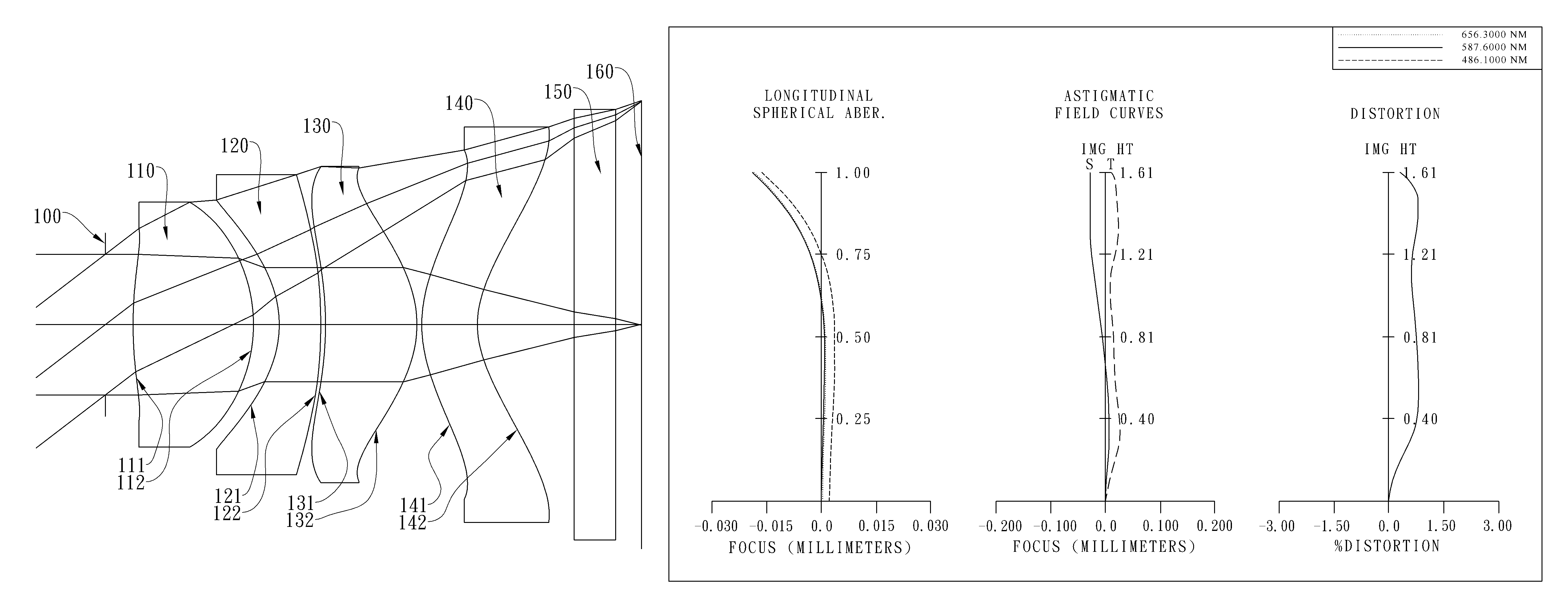
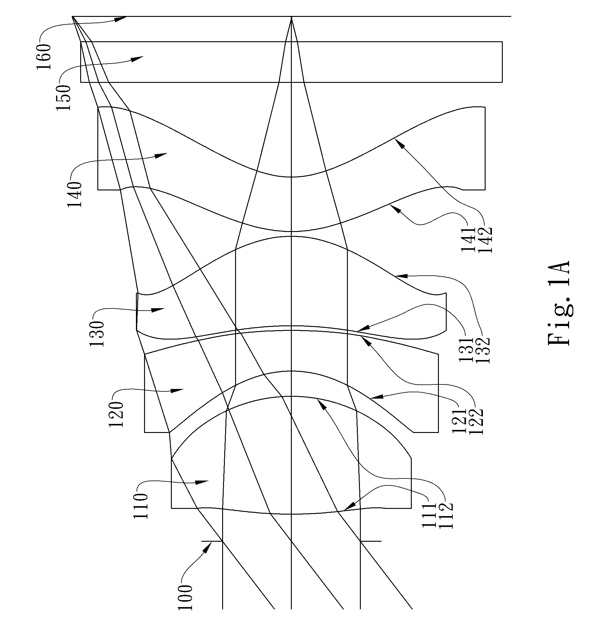
[0049]In present image pick-up optical lens assembly, the effective radius of the object-side surface of the first lens element is Y11, and the effective radius of the image-side surface of the fourth lens element is Y42. The distances and relative locations represented by Y11 and Y42 will be further illustrated in FIG. 11. FIG. 11 is a schematic representation illustrating an image pick-up optical lens assembly in accordance with the present invention. The vertical distance between the farthest point of the effective light entry area on the object-side surface 111 of the first lens element 110 and the optical axis is Y11, and the vertical distance between the farthest point of the effective light entry area on the image-side surface 142 of the fourth lens element 140 and the optical axis is Y42.

[0050]Preferred embodiments of the present invention will be described in the following paragraphs by referring to the accompanying drawings.

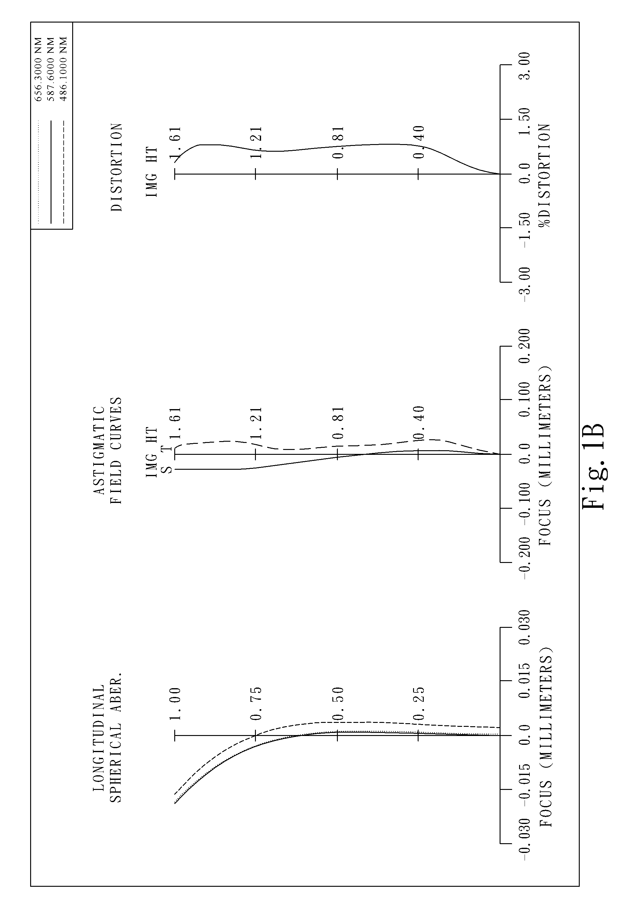
[0051]FIG. 1A shows an image pick-up optical lens...

second embodiment

[0080]In the present image pick-up optical lens assembly, the focal length of the image pick-up optical lens assembly is f, and it satisfies the relation: f=2.12 (mm).

[0081]In the second embodiment of the present image pick-up optical lens assembly, the f-number of the image pick-up optical lens assembly is Fno, and it satisfies the relation: Fno=2.07.

[0082]In the second embodiment of the present image pick-up optical lens assembly, half of the maximal field of view of the image pick-up optical lens assembly is HFOV, and it satisfies the relation: HFOV=36.9 (degrees).

[0083]In the second embodiment of the present image pick-up optical lens assembly, the Abbe number of the first lens element 210 is V1, the Abbe number of the second lens element 220 is V2, and they satisfy the relation: V1−V2=35.1.

[0084]In the second embodiment of the present image pick-up optical lens assembly, the refractive index of the first lens element 210 is N1, the refractive index of the second lens element 22...

third embodiment

[0101]In the present image pick-up optical lens assembly, the focal length of the image pick-up optical lens assembly is f, and it satisfies the relation: f=2.13 (mm).

[0102]In the third embodiment of the present image pick-up optical lens assembly, the f-number of the image pick-up optical lens assembly is Fno, and it satisfies the relation: Fno=2.40.

[0103]In the third embodiment of the present image pick-up optical lens assembly, half of the maximal field of view of the image pick-up optical lens assembly is HFOV, and it satisfies the relation: HFOV=37.3 (degrees).

[0104]In the third embodiment of the present image pick-up optical lens assembly, the Abbe number of the first lens element 310 is V1, the Abbe number of the second lens element 320 is V2, and they satisfy the relation: V1−V2=32.5.

[0105]In the third embodiment of the present image pick-up optical lens assembly, the refractive index of the first lens element 310 is N1, the refractive index of the second lens element 320 is...


PUM


Abstract

This invention provides an image pick-up optical lens assembly comprising, in order from an object side to an image side: a first lens element with positive refractive power having a convex object-side surface and a convex image-side surface; a second lens element with negative refractive power having a concave object-side surface and a convex image-side surface; a third lens element with positive refractive power having an object-side surface and a convex image-side surface, at least one of the surfaces thereof being aspheric; and a fourth lens element with negative refractive power having a convex object-side surface and a concave image-side surface, at least one of the surfaces thereof being aspheric. The image pick-up optical lens assembly further comprises an aperture stop disposed between an object and the first lens element. Such arrangement facilitates a significant reduction in size and sensitivity of the lens assembly while providing superb image quality with higher resolution.

Description

CROSS-REFERENCE TO RELATED APPLICATIONS[0001]This non-provisional application claims priority under 35 U.S.C. §119(a) on Patent Application No(s). 099139905 filed in Taiwan, R.O.C. on Nov. 19, 2010, the entire contents of which are hereby incorporated by reference.BACKGROUND OF THE INVENTION[0002]1. Field of the Invention[0003]The present invention relates to an image pick-up optical lens assembly, and more particularly, to an image pick-up optical lens assembly used in electronic products.[0004]2. Description of the Prior Art[0005]The demand for compact imaging lens elements has grown in recent years as the popularity of portable electronic products with the photographing function has increased, and the sensor of a general imaging lens is none other than CCD (Charge Coupled Device) or CMOS (Complementary Metal-Oxide Semiconductor Sensor). Furthermore, as advances in semiconductor manufacturing technology have allowed the pixel size of sensors to be reduced, and the resolution of co...

Claims


Application Information

Patent Timeline
Patent Type & Authority Patents(United States)
IPC IPC(8): G02B9/34G02B3/02
CPCG02B13/004
Inventor TSAI, TSUNG HANHUANG, HSIN HSUAN
Owner LARGAN PRECISION
Why Eureka
Try Eureka