
Anesthetic solution-filled cartridge-type electric dental syringe

a technology of electric dental syringes and annesthetic solutions, which is applied in the field of annesthetic solution-filled cartridge-type motorized syringes, can solve the problems of long and bulky configuration of motorized syringes

Active Publication Date: 2014-01-09
GC SHOWAYAKUHIN CORP
View PDF1 Cites 2 Cited by
  • Summary
  • Abstract
  • Description
  • Claims
  • Application Information

AI Technical Summary

Benefits of technology

The present invention is a dental anesthetic solution-filled cartridge-type motorized syringe. It has a shorter pusher rod to comply with wishes of users. The pusher rod is moved a necessary distance to deliver anesthetic solution from the cartridge. The invention comprises an extension tube and racks on the pusher rod that engage with a rotating pinion on a drive unit. The pusher rod pulls the extension tube to engage the racks with the pinion when the pusher rod reaches the middle of the cartridge's length, causing the pusher rod to move the remainder of the distance equal to the length of the cartridge's anesthetic solution accommodation. The extension tube, which is movably located in a support block, assists in delivering the anesthetic solution to the dental area. The technical effect of the invention is to provide a dental anesthetic solution-filled cartridge-type motorized syringe that is easy to use and efficient in delivering anesthetic solution to the dental area.

Problems solved by technology

To this end, the pusher rod for the motorized syringe must be long in size, and consequently, the motorized syringe must be designed in a long and bulky configuration.

Method used


Image

  • Anesthetic solution-filled cartridge-type electric dental syringe
  • Anesthetic solution-filled cartridge-type electric dental syringe
  • Anesthetic solution-filled cartridge-type electric dental syringe

Examples


Embodiment Construction

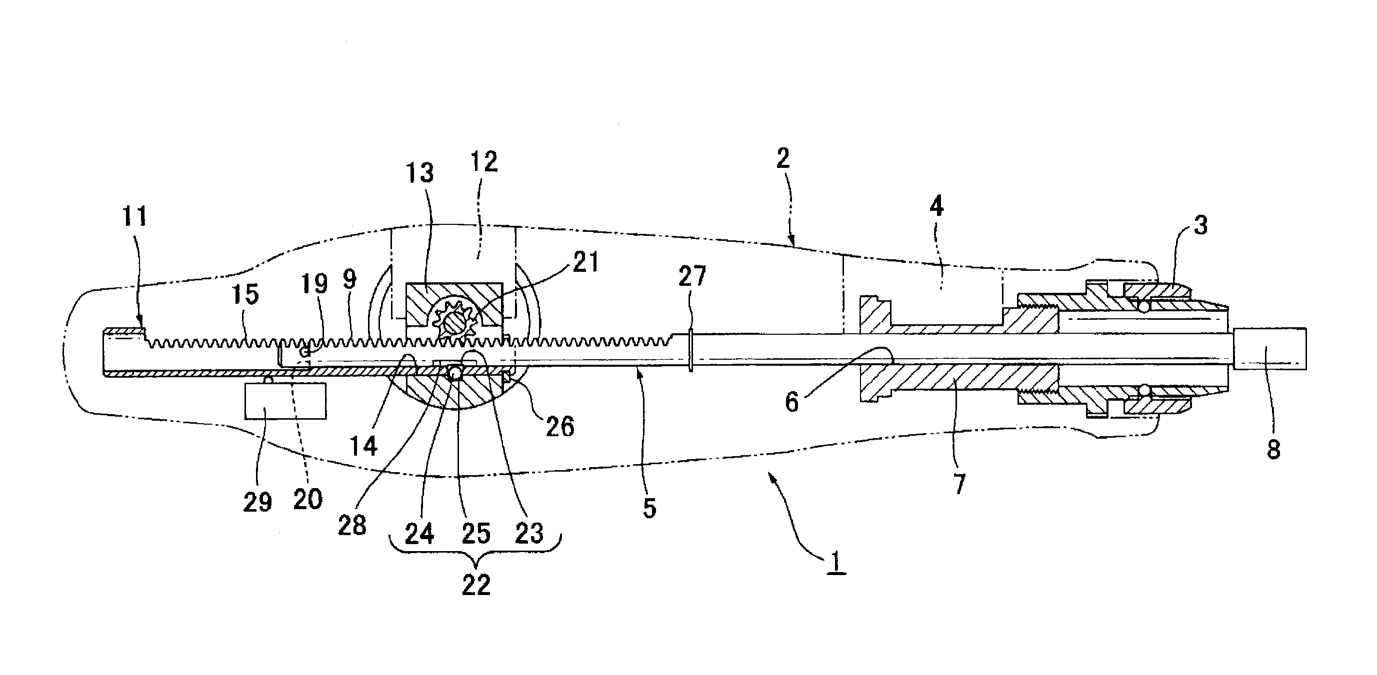
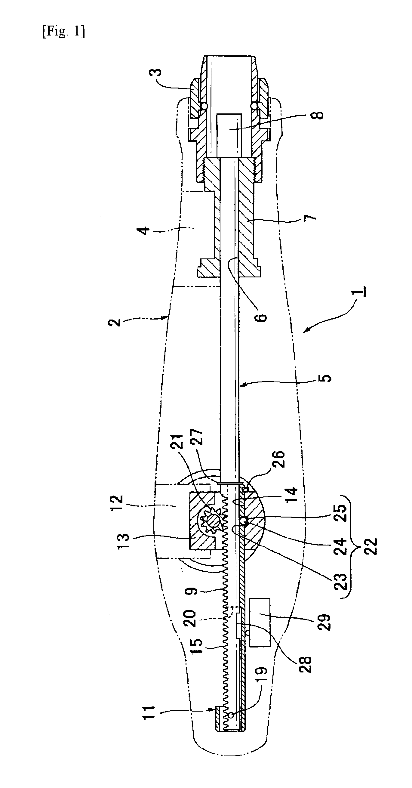
[0016]Referring to FIG. 1 of the drawings, a motorized syringe 1 embodied in accordance with the invention includes a syringe body 2 as generally indicated in a dotted line and a coupling 3 for detachably connecting a cartridge holder (not shown) to the forward end of the syringe body, the cartridge holder having an anesthetic solution-filled cartridge (not shown) loaded thereinto. The coupling 3 is threadedly affixed to a support member 7 secured to a mounting block 4 and having a through-hole 6 through which a metallic round pusher rod 5 is passed.

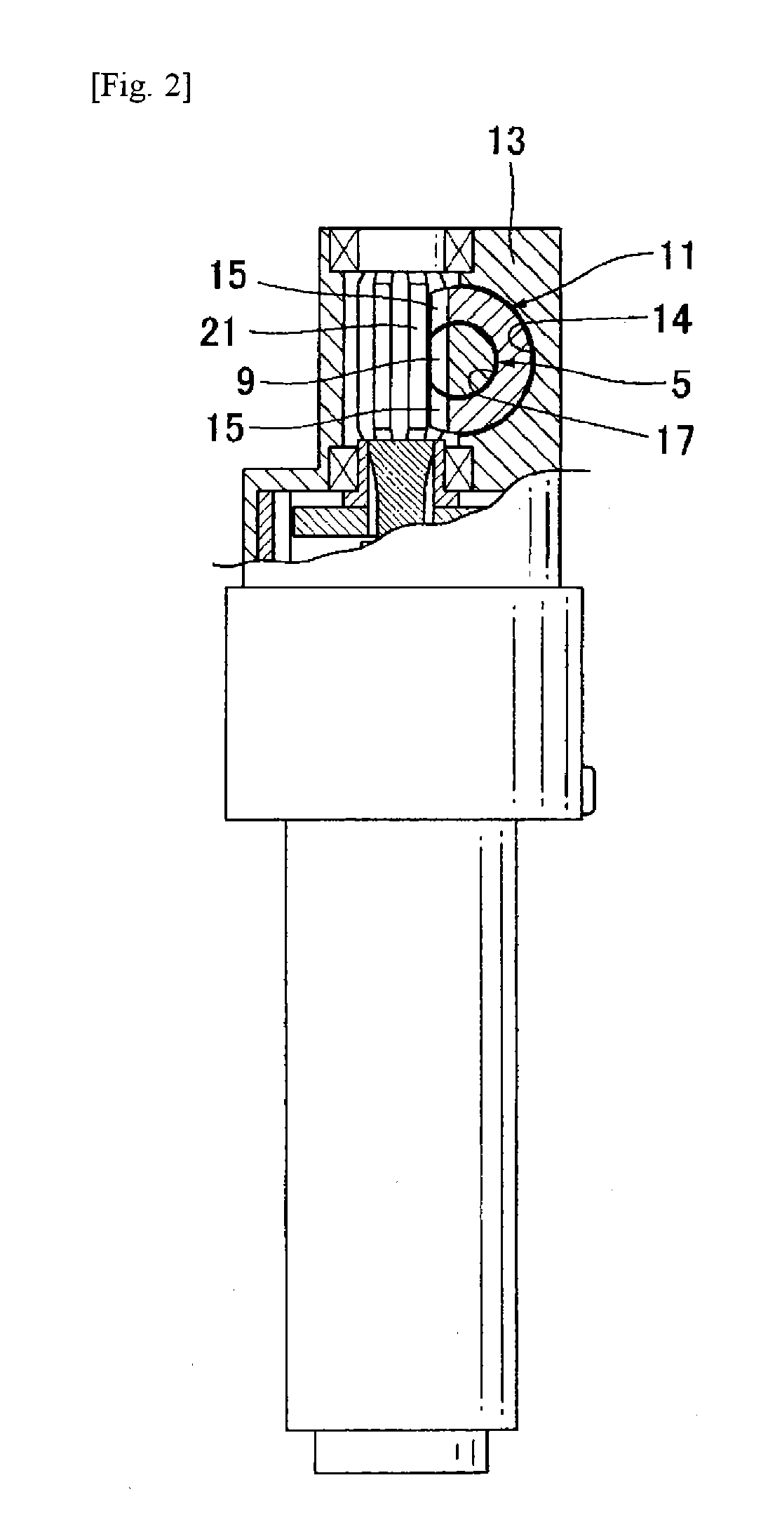
[0017]As shown in FIG. 1 and FIGS. 3-6, pusher rod 5 is provided with an enlarged head 8 adapted to abut a plunger rubber plug (not shown) in the cartridge, from behind, and is formed on its rearward portion with a flat rack 9 on one side of pusher rod 5. As can be seen in FIGS. 1-4, a metallic extension tube 11 is movably inserted in a through hole 14 in a support block 12 affixed to a mounting block of syringe body 2, such that pusher ...


PUM


Abstract

Provided is an anesthetic solution-filled cartridge-type electric dental syringe, wherein the plunger has been shortened but the plunger can nevertheless be extended to the distance necessary to evacuate the anesthetic solution from the cartridge. The syringe comprises: an extension tube (11) into which a plunger (5) is movably inserted, the extension tube being movably disposed in the through hole (14) of a support block (13) and having racks (15, 15) formed in the side surface thereof that are coordinated with the racks (9) of the plunger; and a means for the plunger to draw the extension tube to engage the racks (15, 15) of the extension tube with a pinion (21) when the plunger reaches the middle of the distance corresponding to the anesthetic solution accommodation length of the cartridge. By the engagement of the racks of the extension tube with the pinion, the plunger moves together with the extension tube for the remainder of the distance corresponding to the anesthetic solution accommodation length of the cartridge.

Description

TECHNICAL FIELD[0001]This invention relates to anesthetic solution-filled cartridge-type motorized syringes, and particularly, to such a motorized syringe in which an improved pusher rod is incorporated to push a plunger rubber plug in the cartridge for delivery of the anesthetic solution filled in the cartridge.BACKGROUND OF THE INVENTION[0002]The cartridge is made of glass and has a dental anesthetic solution filled therein for local anesthesia. There are cartridges of 1.8 ml and 1.0 ml of anesthetic in volume and they are different in length due to the different volumes of anesthetic and due to the fact that the cartridges have identical inner and outer diameters.[0003]In either case, a motorized syringe may used for administration of anesthesia by loading a cartridge into a cartridge holder, detachably connecting the cartridge holder to a coupling of the motorized syringe, and affixing a double pointed needle to the tip of the cartridge. The motorized syringe comprises a pusher ...

Claims


Application Information

Patent Timeline
IPC IPC(8): A61M5/20
CPCA61M5/20A61M5/24A61M5/31511A61M2005/31518A61C19/08A61C5/62
Inventor TANAKA, FUMIOHARAGUCHI, MITSUHIROKAWASAKI, YOSHIHIKOSHIBUYA, MUTSUMIHAYASHI, RENJIKATO, YOSHINORI
Owner GC SHOWAYAKUHIN CORP
Learn More